Home /
Expert Answers /
Electrical Engineering /
using-the-simple-piecewise-linear-diode-model-shown-in-figure-1-with-v-f-0-7-mathrm-v-an-pa263
(Solved): Using the simple piecewise-linear diode model shown in Figure 1 with \( V_{f}=0.7 \mathrm{~V} \) an ...
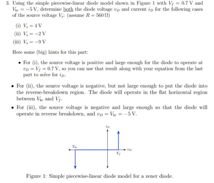
Using the simple piecewise-linear diode model shown in Figure 1 with \( V_{f}=0.7 \mathrm{~V} \) and \( V_{b r}=-5 \mathrm{~V} \), determine both the diode voltage \( v_{D} \) and current \( i_{D} \) for the following cases of the source voltage \( V_{s:} \) (assume \( R=560 \Omega \) ) (i) \( V_{s}=4 \mathrm{~V} \) (ii) \( V_{s}=-2 \mathrm{~V} \) (iii) \( V_{s}=-9 \mathrm{~V} \) Here some (big) hints for this part: - For (i), the source voltage is positive and large enough for the diode to operate at \( v_{D}=V_{f}=0.7 \mathrm{~V} \), so you can use that result along with your equation from the last part to solve for \( i_{D} \). - For (ii), the source voltage is negative, but not large enough to put the diode into the reverse-breakdown region. The diode will operate in the flat horizontal region between \( V_{b r} \) and \( V_{f} \). - For (iii), the source voltage is negative and large enough so that the diode will operate in reverse breakdown, and \( v_{D}=V_{b r}=-5 \mathrm{~V} \). Figure 1: Simple piecewise-linear diode model for a zener diode.