Home /
Expert Answers /
Electrical Engineering /
use-ltspice-create-a-schematic-diagram-1-single-transistor-motor-driver-design-specificaton-v-pa319
(Solved): Use LTSpice create a schematic diagram 1 Single Transistor Motor Driver Design Specificaton: V ...
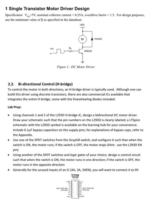
Use LTSpice create a schematic diagram
1 Single Transistor Motor Driver Design Specificaton: , nominal collector current , overdrive factor . For design purposes, use the minimum value of as specified in the datasheet. 2.2. Bi-directional Control (H-bridge) To control the motor in both directions, an H-bridge driver is typically used. Although one can build this driver using discrete transistors, there are also commercial ICs available that integrates the entire -bridge, some with the freewheeling diodes included. Lab Prep: - Using channels 1 and 2 of the L293D H-bridge IC, design a bidirectional DC motor driver. Draw your schematic such that the pin numbers on the L293D is clearly labeled; a LTSpice schematic with the L293D symbol is available on the learning hub for your convenience. Include bypass capacitors on the supply pins; for explanations of bypass caps, refer to the Appendix. - Use one of the SPDT switches from the Grayhill switch, and configure it such that when the switch is ON, the motor runs; if the switch is OFF, the motor stops (Hint: use the L293D EN pin) - Using another of the SPDT switches and logic gates of your choice, design a control circuit such that when the switch is ON, the motor runs in one direction; if the switch is OFF, the motor runs in the opposite direction - Generally for the unused inputs of an IC (4A, ), you will want to connect it to OV