Home /
Expert Answers /
Electrical Engineering /
university-of-technology-and-applied-sciences-nizwa-3-for-the-circuit-shown-in-the-figure-below-pa877
(Solved): University of Technology and Applied Sciences - Nizwa 3. For the circuit shown in the figure below ...
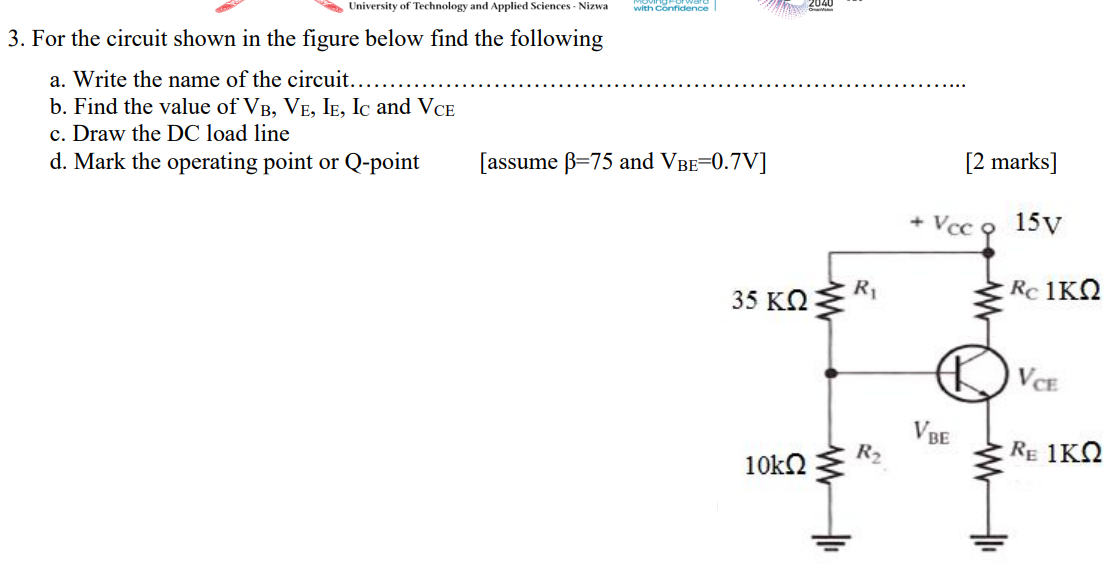
University of Technology and Applied Sciences - Nizwa 3. For the circuit shown in the figure below find the following a. Write the name of the circuit.. b. Find the value of VB, VE, IE, IC and VCE c. Draw the DC load line d. Mark the operating point or Q-point with Confidence [assume B=75 and VBE=0.7V] 35 ?? 10kQ2 R? R? + [2 marks] Vcc 9 15v VBE R 1?? VCE RE 1KQ