Home /
Expert Answers /
Advanced Physics /
two-neutral-conductors-are-shown-in-figure-3-below-the-objects-are-not-interacting-with-each-oth-pa414
(Solved): Two neutral conductors are shown in Figure 3 below. (The objects are not interacting with each oth ...
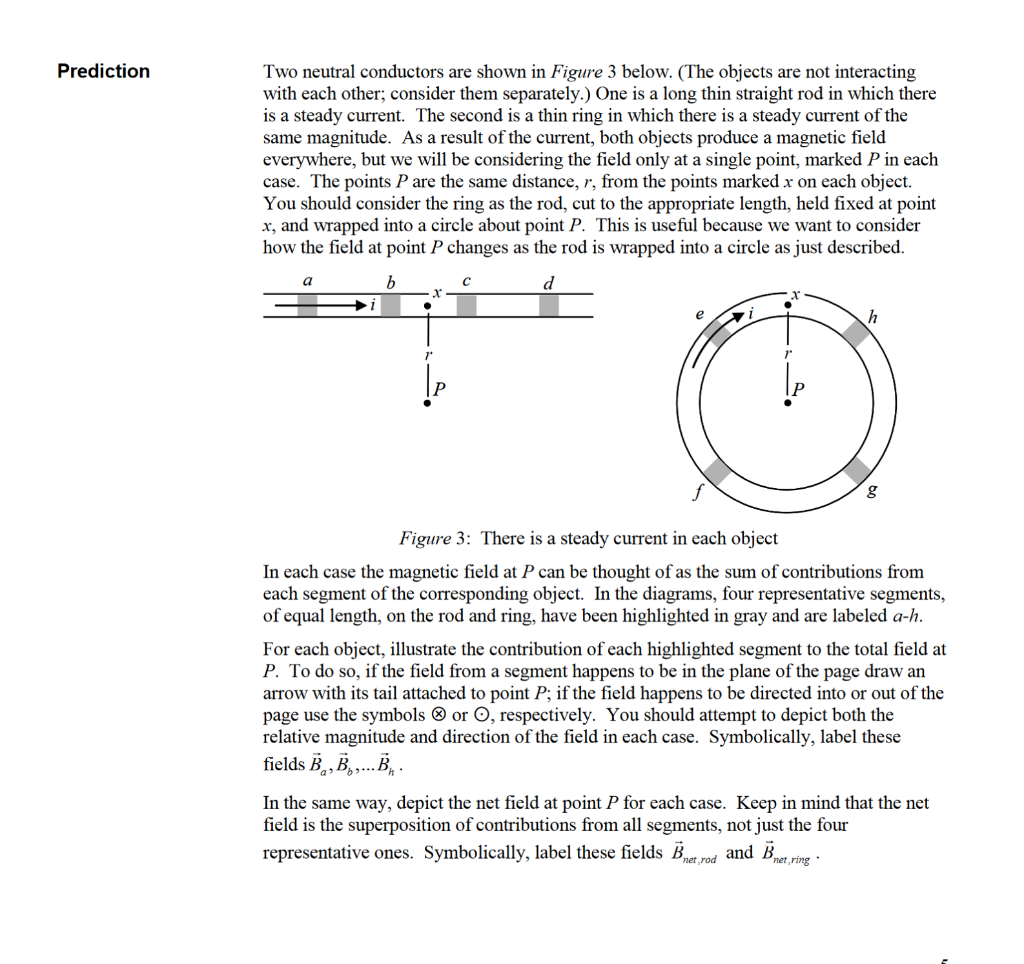
Two neutral conductors are shown in Figure 3 below. (The objects are not interacting with each other; consider them separately.) One is a long thin straight rod in which there is a steady current. The second is a thin ring in which there is a steady current of the same magnitude. As a result of the current, both objects produce a magnetic field everywhere, but we will be considering the field only at a single point, marked \( P \) in each case. The points \( P \) are the same distance, \( r \), from the points marked \( x \) on each object. You should consider the ring as the rod, cut to the appropriate length, held fixed at point \( x \), and wrapped into a circle about point \( P \). This is useful because we want to consider how the field at point \( P \) changes as the rod is wrapped into a circle as just described. Figure 3: There is a steady current in each object In each case the magnetic field at \( P \) can be thought of as the sum of contributions from each segment of the corresponding object. In the diagrams, four representative segments, of equal length, on the rod and ring, have been highlighted in gray and are labeled \( a-h \). For each object, illustrate the contribution of each highlighted segment to the total field at \( P \). To do so, if the field from a segment happens to be in the plane of the page draw an arrow with its tail attached to point \( P \); if the field happens to be directed into or out of the page use the symbols \( \otimes \) or \( \odot \), respectively. You should attempt to depict both the relative magnitude and direction of the field in each case. Symbolically, label these fields \( \vec{B}_{a}, \vec{B}_{b}, \ldots \vec{B}_{h} \). In the same way, depict the net field at point \( P \) for each case. Keep in mind that the net field is the superposition of contributions from all segments, not just the four representative ones. Symbolically, label these fields \( \vec{B}_{\text {net,rod }} \) and \( \vec{B}_{\text {net,ring }} \).
Check your thinking Your additions to the diagram should unambiguously illustrate the direction of each field vector. Whether you were successful in depicting their relative magnitudes or not, make your intention clear by ranking all ten vectors from greatest to least in magnitude. If any have the same magnitude, give them the same ranking. Write down your ranking in the box below. Summarize 3. Do you predict the net magnetic field at point \( P \) for the ring to be greater, less or equal in magnitude to the field at point \( P \) for the rod? 4. In words, describe what you think is happening to the net field at \( P \) when the rod is bent into a circle. 5. How is this case the same as the analogous electrostatics case? How is it different?