Home /
Expert Answers /
Electrical Engineering /
the-variable-load-resistor-r-in-the-circuit-shown-in-the-figure-adjusted-for-maximum-average-p-pa647
(Solved): The variable load resistor R, in the circuit shown in the figure adjusted for maximum average p ...
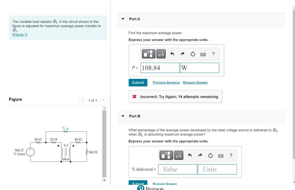
The variable load resistor R?, in the circuit shown in the figure adjusted for maximum average power transfer to R?.. (Figure 1) < 1 of 1 Figure 500/0° V (rms) 8002 ww 2002 ww . R?4 m 1:2 || Ideal 40 ? m ? 3.360 ? 0 Part A Find the maximum average power. Express your answer with the appropriate units. ? ?A 6 www. ? P= 108.84 W Submit Previous Answers Request Answer * Incorrect; Try Again; 14 attempts remaining ? Part B What percentage of the average power developed by the ideal voltage source is delivered to R? when R? is absorbing maximum average power? Express your answer with the appropriate units. HA B ? % delivered = Value Units Submit Request Answer Pearson
