Home /
Expert Answers /
Civil Engineering /
the-truss-is-hinged-supported-by-25-mathrm-ft-long-columns-as-shown-in-figure-1-the-co-pa242
(Solved): The truss is hinged supported by \( 25 \mathrm{ft} \). long columns, as shown in Figure 1 . The co ...
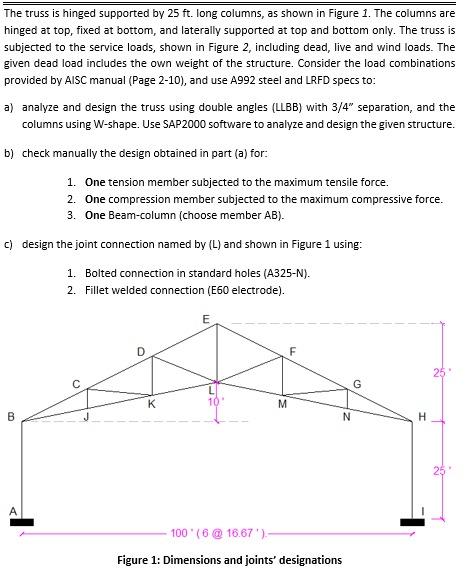
The truss is hinged supported by \( 25 \mathrm{ft} \). long columns, as shown in Figure 1 . The columns are hinged at top, fixed at bottom, and laterally supported at top and bottom only. The truss is subjected to the service loads, shown in Figure 2, including dead, live and wind loads. The given dead load includes the own weight of the structure. Consider the load combinations provided by AISC manual (Page 2-10), and use A992 steel and LRFD specs to: a) analyze and design the truss using double angles (LLBB) with \( 3 / 4^{\prime \prime} \) separation, and the columns using W-shape. Use SAP2000 software to analyze and design the given structure. b) check manually the design obtained in part (a) for: 1. One tension member subjected to the maximum tensile force. 2. One compression member subjected to the maximum compressive force. 3. One Beam-column (choose member AB). c) design the joint connection named by (L) and shown in Figure 1 using: 1. Bolted connection in standard holes (A325-N). 2. Fillet welded connection (E60 electrode). Figure 1: Dimensions and joints' designations
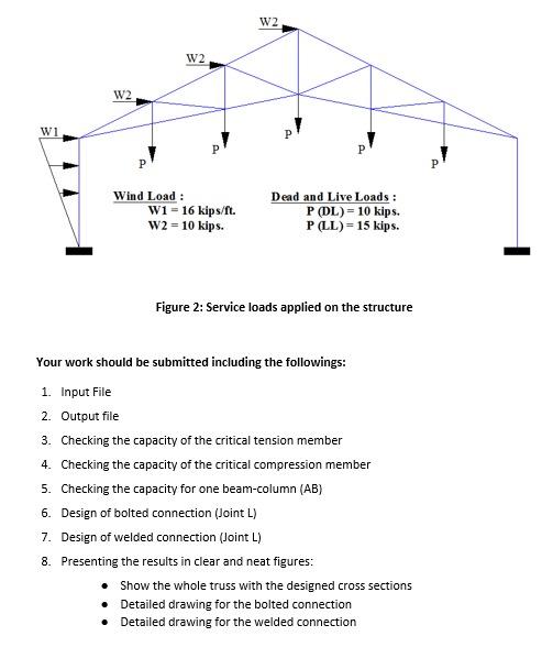
Figure 2: Service loads applied on the structure Your work should be submitted including the followings: 1. Input File 2. Output file 3. Checking the capacity of the critical tension member 4. Checking the capacity of the critical compression member 5. Checking the capacity for one beam-column (AB) 6. Design of bolted connection (Joint \( \mathrm{L} \) ) 7. Design of welded connection (Joint \( \mathrm{L} \) ) 8. Presenting the results in clear and neat figures: - Show the whole truss with the designed cross sections - Detailed drawing for the bolted connection - Detailed drawing for the welded connection
Expert Answer
Solution:- Given Data :- Please refer to this step for solution according to the given data.