Home /
Expert Answers /
Mechanical Engineering /
the-trailer-hitch-from-figure-1-1-has-loads-applied-as-shown-in-figure-p3-2-4-4-the-trailer-hitch-f-pa353
(Solved): The trailer hitch from Figure 1-1 has loads applied as shown in Figure P3-2. 4-4 The trailer hitch f ...
The trailer hitch from Figure 1-1 has loads applied as shown in Figure P3-2.
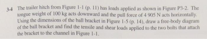
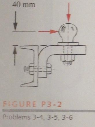
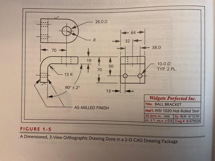
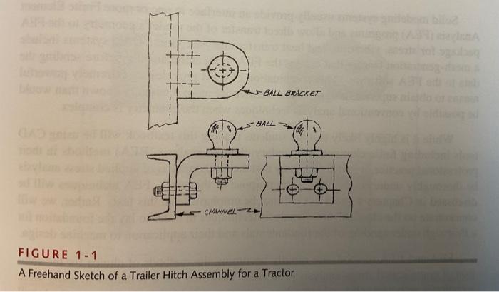
4-4 The trailer hitch from Figure 1-1 (p. 11) has loads applied as shown in Figure P3-2. The tongue weight of \( 100 \mathrm{~kg} \) acts downward and the pull force of \( 4905 \mathrm{~N} \) acts horizontally. Using the dimensions of the ball bracket in Figure 1-5 (p. 14), draw a free-body diagram of the ball bracket and find the tensile and shear loads applied to the two bolts that attach the bracket to the channel in Figure 1-1.
A Dimensioned, 3-View Orthographic Drawing Done in a 2-D CAD Drawing Package
A Freehand Sketch of a Trailer Hitch Assembly for a Tractor