Home /
Expert Answers /
Mechanical Engineering /
the-steel-tie-bar-shown-in-the-figure-has-been-designed-to-carry-a-tension-force-of-117-mathrm-pa217
(Solved): The steel tie-bar shown in the figure has been designed to carry a tension force of 117 \( \mathrm{ ...
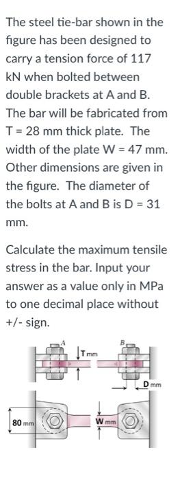
The steel tie-bar shown in the figure has been designed to carry a tension force of 117 \( \mathrm{kN} \) when bolted between double brackets at A and B. The bar will be fabricated from \( \mathrm{T}=28 \mathrm{~mm} \) thick plate. The width of the plate \( W=47 \mathrm{~mm} \). Other dimensions are given in the figure. The diameter of the bolts at \( A \) and \( B \) is \( D=31 \) \( \mathrm{mm} \). Calculate the maximum tensile stress in the bar. Input your answer as a value only in MPa to one decimal place without \( + \) - sign.
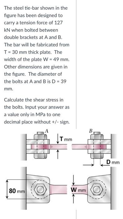
The steel tie-bar shown in the figure has been designed to carry a tension force of 127 kN when bolted between double brackets at \( \mathrm{A} \) and \( \mathrm{B} \). The bar will be fabricated from \( \mathrm{T}=30 \mathrm{~mm} \) thick plate. The width of the plate \( \mathrm{W}=49 \mathrm{~mm} \). Other dimensions are given in the figure. The diameter of the bolts at \( A \) and \( B \) is \( D=39 \) \( \mathrm{mm} \). Calculate the shear stress in the bolts. Input your answer as a value only in MPa to one decimal place without \( +/- \) sign.
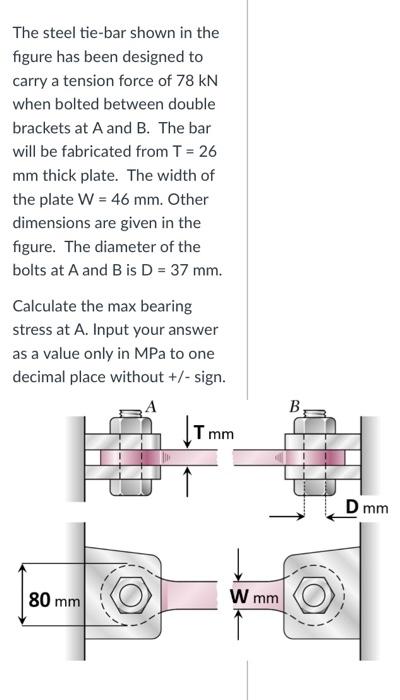
The steel tie-bar shown in the figure has been designed to carry a tension force of \( 78 \mathrm{kN} \) when bolted between double brackets at \( A \) and \( B \). The bar will be fabricated from \( T=26 \) \( \mathrm{mm} \) thick plate. The width of the plate \( \mathrm{W}=46 \mathrm{~mm} \). Other dimensions are given in the figure. The diameter of the bolts at \( A \) and \( B \) is \( D=37 \mathrm{~mm} \). Calculate the max bearing stress at A. Input your answer as a value only in MPa to one decimal place without \( +/- \) sign.