Home /
Expert Answers /
Civil Engineering /
the-point-loads-are-placed-at-the-fixed-positions-shown-in-the-figure-and-they-are-live-loads-pa470
(Solved): The point loads are placed at the fixed positions shown in the figure and they are live loads. \[ ...
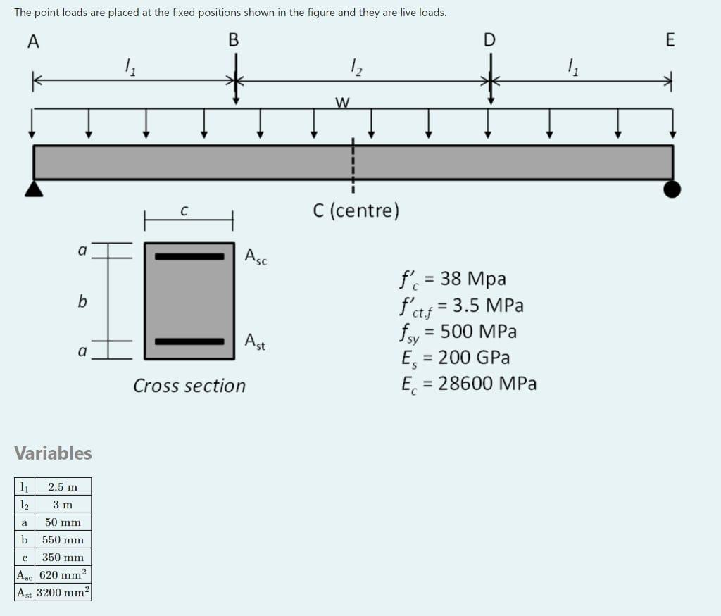
The point loads are placed at the fixed positions shown in the figure and they are live loads. \[ \begin{array}{l} f_{c}^{\prime}=38 \mathrm{Mpa} \\ f_{c t . f}^{\prime}=3.5 \mathrm{MPa} \\ f_{s y}=500 \mathrm{MPa} \\ E_{s}=200 \mathrm{GPa} \\ E_{c}=28600 \mathrm{MPa} \end{array} \] Variables
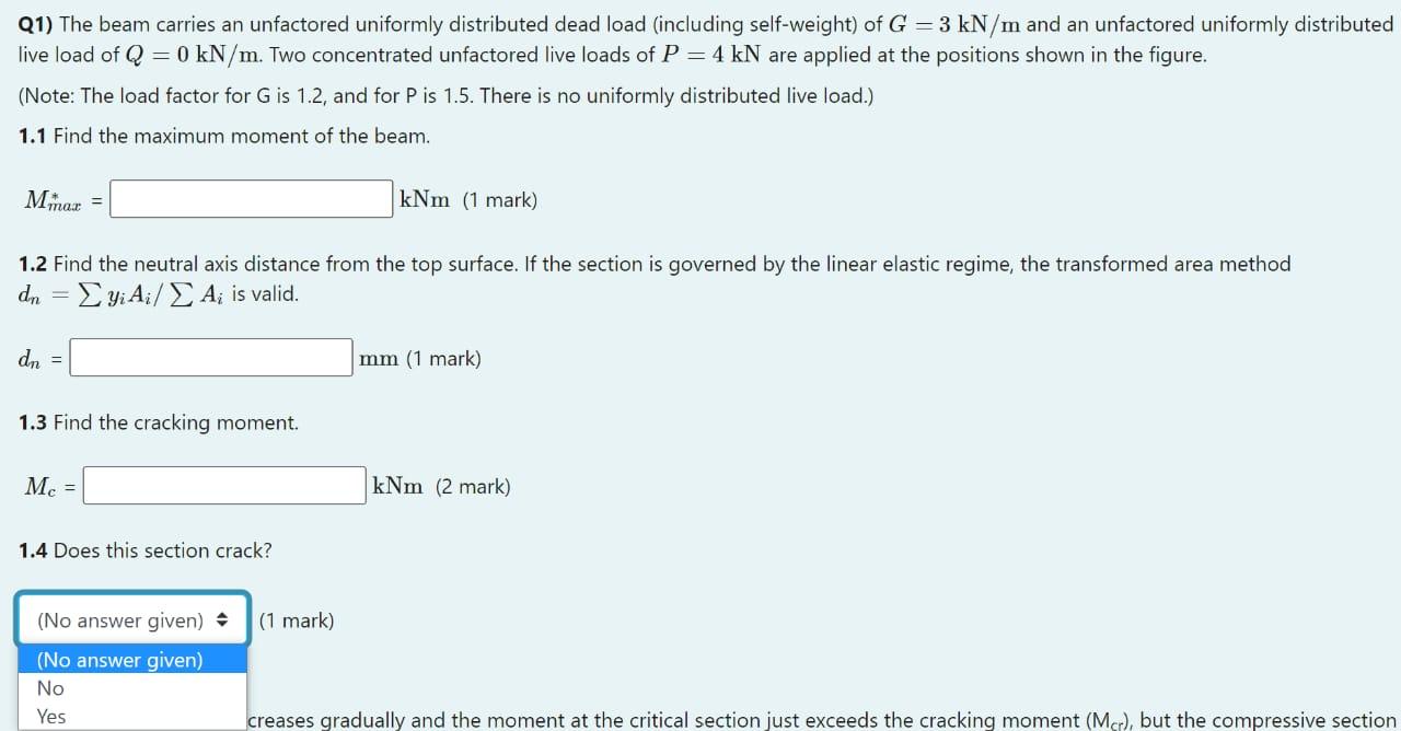
Q1) The beam carries an unfactored uniformly distributed dead load (including self-weight) of \( G=3 \mathrm{kN} / \mathrm{m} \) and an unfactored uniformly distribu live load of \( Q=0 \mathrm{kN} / \mathrm{m} \). Two concentrated unfactored live loads of \( P=4 \mathrm{kN} \) are applied at the positions shown in the figure. (Note: The load factor for \( G \) is \( 1.2 \), and for \( P \) is \( 1.5 \). There is no uniformly distributed live load.) 1.1 Find the maximum moment of the beam. 1.2 Find the neutral axis distance from the top surface. If the section is governed by the linear elastic regime, the transformed area method \( d_{n}=\sum y_{i} A_{i} / \sum A_{i} \) is valid. \[ d_{n}= \] \( 1.3 \) Find the cracking moment. \[ M_{c}= \] 1.4 Does this section crack? \[ \text { (1 mark) } \] creases gradually and the moment at the critical section just exceeds the cracking moment \( \left(M_{c r}\right) \), but the compressive sec