Home /
Expert Answers /
Mechanical Engineering /
the-object-tracking-system-shown-in-fig-1-consists-of-a-computer-controlled-tilt-table-on-which-a-pa841
(Solved): The object-tracking system shown in Fig. 1 consists of a computer-controlled tilt table on which a ...
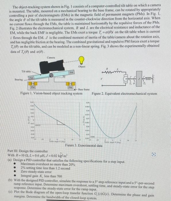
The object-tracking system shown in Fig. 1 consists of a computer-controlled tilt table on which a camera is mounted. The table, mounted on a mechanical bearing to the base frame, can be rotated by appropriately controlling a pair of electromagnets (EMs) in the magnetic field of permanent magnets (PMs). In Fig. 1 , the angle of the tilt table is measured in the counter-clockwise direction from the horizontal axis. When no current flows through the EMs, the table is maintained horizontally by the repulsive forces of the PMs. Fig, 2 illustrates the electromechanical system, and are the electrical resistance and inductance of the EM, while the back EMF is negligible. The EMs exert a torque on the tilt table when is current if flows through the EM. is the combined moment of inertia of the table/camera about the rotation axis, and has negligible friction at the bearing. The combined gravitational and repulsive PM forces exert a torque on the tilt table, and can be modeled as a non-linear spring. Fig. 3 shows the experimentally obtained data of and . rigure 1, vision-baseu object tracking system Figure 2. Equivalent electromechanical system Part III: Design the controller With (a) Design a PID controller that satisfies the following specifications for a step input. - Maximum overshoot no more than - setting time less than second Zero steady-state error Integral gain , less than 700 (b) With the designed PID controller, simulate the response to a step reference input and a -per-second ramp reference input. Determine maximum overshoot, settling time, and steady-state error for the step response. Determine the steady-state error for the ramp input. (c) Plot the Bode diagram of the open-loop transfer function . Determine the phase and gain margins. Determine the bandwidth of the elosed-loop system.
Expert Answer
Answer. The object-tracking system sh