Home /
Expert Answers /
Electrical Engineering /
the-lna-simplified-shown-below-is-designed-to-operate-with-low-supply-voltages-each-inductor-is-pa152
(Solved): The LNA (simplified) shown below is designed to operate with low supply voltages. Each inductor is ...
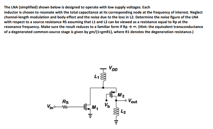
The LNA (simplified) shown below is designed to operate with low supply voltages. Each inductor is chosen to resonate with the total capacitance at its corresponding node at the frequency of interest. Neglect channel-length modulation and body effect and the noise due to the loss in L2. Determine the noise figure of the LNA with respect to a source resistance \( \mathrm{RS} \) assuming that \( \mathbf{L 1} \) and \( \mathbf{L} \mathbf{2} \) can be viewed as a resistance equal to \( \mathrm{Rp} \) at the resonance frequency. Make sure the result reduces to a familiar form if \( \mathrm{Rp} \rightarrow \infty \). (Hint: the equivalent transconductance of a degenerated common-source stage is given by gm/(1+gmR1), where R1 denotes the degeneration resistance.)