Home /
Expert Answers /
Mechanical Engineering /
the-following-figure-shows-a-crank-loaded-by-a-force-mathrm-f-400-lbf-that-causes-twisting-pa158
(Solved): The following figure shows a crank loaded by a force \( \mathrm{F}=400 \) lbf that causes twisting ...
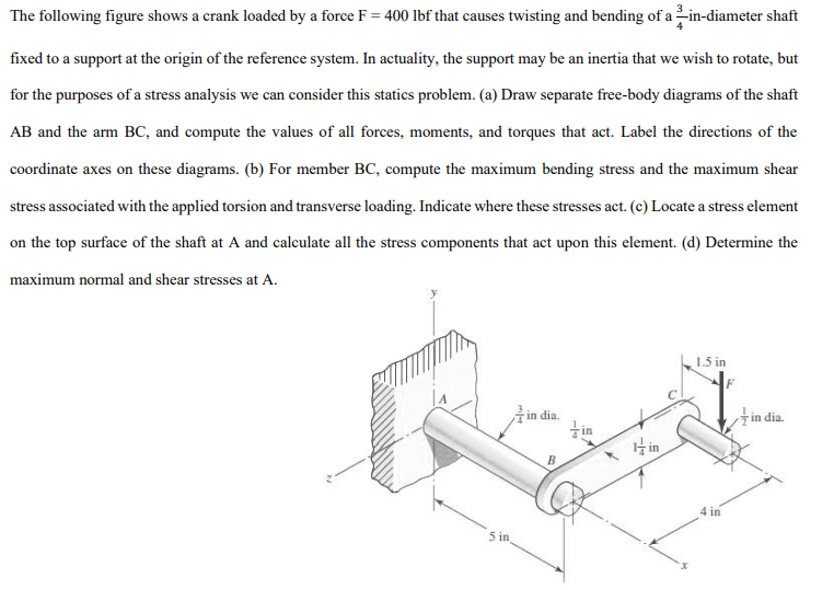
The following figure shows a crank loaded by a force \( \mathrm{F}=400 \) lbf that causes twisting and bending of a \( \frac{3}{4} \) in-diameter shaft fixed to a support at the origin of the reference system. In actuality, the support may be an inertia that we wish to rotate, but for the purposes of a stress analysis we can consider this statics problem. (a) Draw separate free-body diagrams of the shaft \( \mathrm{AB} \) and the arm \( \mathrm{BC} \), and compute the values of all forces, moments, and torques that act. Label the directions of the coordinate axes on these diagrams. (b) For member BC, compute the maximum bending stress and the maximum shear stress associated with the applied torsion and transverse loading. Indicate where these stresses act. (c) Locate a stress element on the top surface of the shaft at \( \mathrm{A} \) and calculate all the stress components that act upon this element. (d) Determine the maximum normal and shear stresses at \( \mathrm{A} \).