Home /
Expert Answers /
Electrical Engineering /
someone-please-build-a-the-circuit-on-a-breadboard-with-labeling-i-will-like-if-done-neatly-light-ac-pa468
(Solved): someone please build a the circuit on a breadboard with labeling.i will like if done neatly Light-ac ...
someone please build a the circuit on a breadboard with labeling.
i will like if done neatly
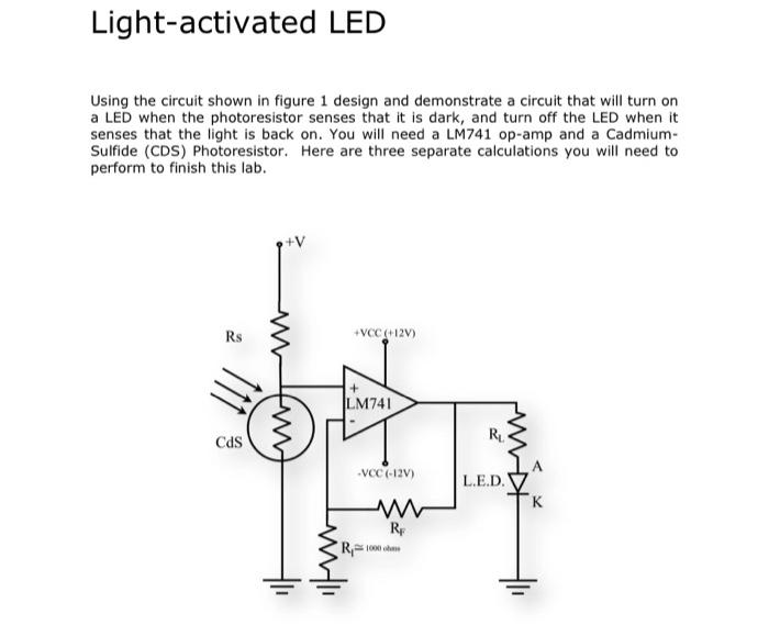
Light-activated LED Using the circuit shown in figure 1 design and demonstrate a circuit that will turn on a LED when the photoresistor senses that it is dark, and turn off the LED when it senses that the light is back on. You will need a LM741 op-amp and a CadmiumSulfide (CDS) Photoresistor. Here are three separate calculations you will need to perform to finish this lab.
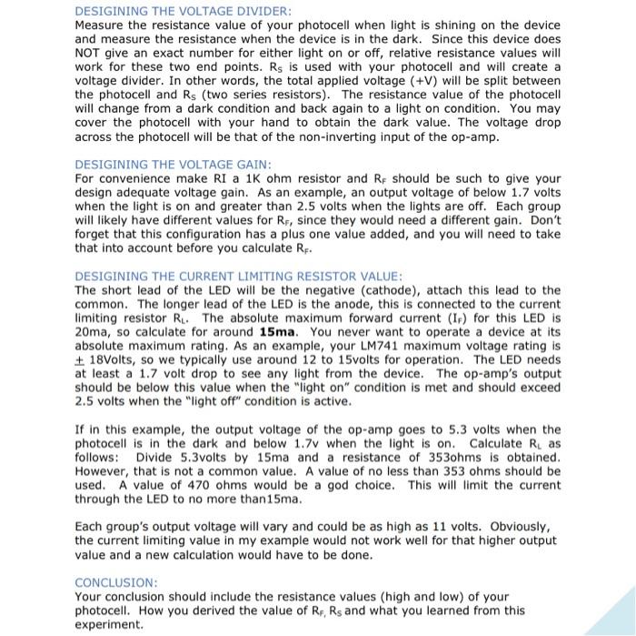
DESIGINING THE VOLTAGE DIVIDER: Measure the resistance value of your photocell when light is shining on the device and measure the resistance when the device is in the dark. Since this device does NOT give an exact number for either light on or off, relative resistance values will work for these two end points. \( \mathrm{R}_{\mathrm{s}} \) is used with your photocell and will create a voltage divider. In other words, the total applied voltage \( (+\mathrm{V}) \) will be split between the photocell and \( R_{S} \) (two series resistors). The resistance value of the photocell will change from a dark condition and back again to a light on condition. You may cover the photocell with your hand to obtain the dark value. The voltage drop across the photocell will be that of the non-inverting input of the op-amp. DESIGINING THE VOLTAGE GAIN: For convenience make RI a \( 1 \mathrm{~K} \) ohm resistor and \( R_{F} \) should be such to give your design adequate voltage gain. As an example, an output voltage of below \( 1.7 \) volts when the light is on and greater than \( 2.5 \) volts when the lights are off. Each group will likely have different values for \( \mathrm{R}_{\mathrm{F}} \), since they would need a different gain. Don't forget that this configuration has a plus one value added, and you will need to take that into account before you calculate \( R_{F} \). DESIGINING THE CURRENT LIMITING RESISTOR VALUE: The short lead of the LED will be the negative (cathode), attach this lead to the common. The longer lead of the LED is the anode, this is connected to the current limiting resistor \( R_{L} \). The absolute maximum forward current ( \( I_{F} \) ) for this LED is 20ma, so calculate for around \( \mathbf{1 5 m a} \). You never want to operate a device at its absolute maximum rating. As an example, your LM741 maximum voltage rating is \( \pm 18 \) Volts, so we typically use around 12 to 15 volts for operation. The LED needs at least a \( 1.7 \) volt drop to see any light from the device. The op-amp's output should be below this value when the "light on" condition is met and should exceed \( 2.5 \) volts when the "light off" condition is active. If in this example, the output voltage of the op-amp goes to \( 5.3 \) volts when the photocell is in the dark and below \( 1.7 \mathrm{v} \) when the light is on. Calculate \( R_{\mathrm{L}} \) as follows: Divide \( 5.3 \) volts by \( 15 \mathrm{ma} \) and a resistance of \( 3530 \mathrm{mms} \) is obtained. However, that is not a common value. A value of no less than 353 ohms should be used. A value of 470 ohms would be a god choice. This will limit the current through the LED to no more than \( 15 \mathrm{ma} \). Each group's output voltage will vary and could be as high as 11 volts. Obviously, the current limiting value in my example would not work well for that higher output value and a new calculation would have to be done. CONCLUSION: Your conclusion should include the resistance values (high and low) of your photocell. How you derived the value of \( R_{F}, R_{s} \) and what you learned from this experiment.
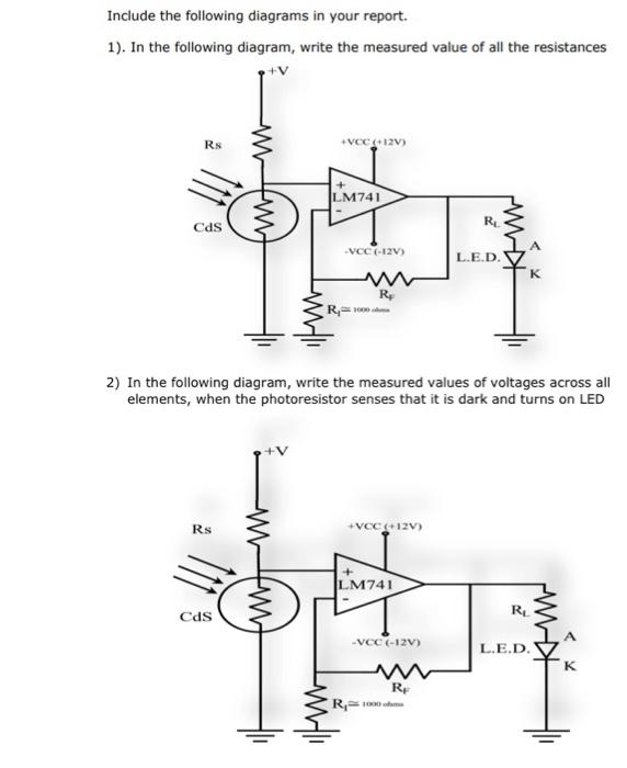
Include the following diagrams in your report. 1). In the following diagram, write the measured value of all the resistances 2) In the following diagram, write the measured values of voltages across all elements, when the photoresistor senses that it is dark and turns on LED
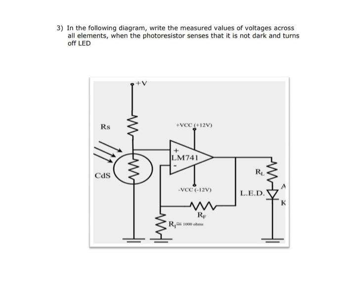
3) In the following diagram, write the measured values of voltages across all elements, when the photoresistor senses that it is not dark and turns off LED
Expert Answer
Answer Next step is the answer for the given problem,