Home /
Expert Answers /
Electrical Engineering /
shown-in-figure-0-1-is-a-diagram-of-a-circuit-used-to-generate-a-large-pulsed-magnetic-field-pa663
(Solved): Shown in Figure \( 0.1 \) is a diagram of a circuit used to generate a large pulsed magnetic field ...
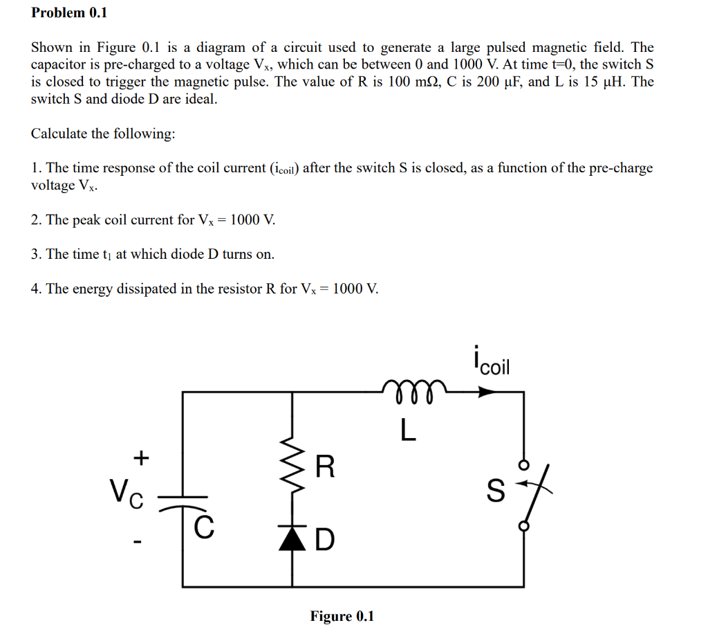
Shown in Figure \( 0.1 \) is a diagram of a circuit used to generate a large pulsed magnetic field. The capacitor is pre-charged to a voltage \( \mathrm{V}_{\mathrm{x}} \), which can be between 0 and \( 1000 \mathrm{~V} \). At time \( \mathrm{t}=0 \), the switch \( \mathrm{S} \) is closed to trigger the magnetic pulse. The value of \( \mathrm{R} \) is \( 100 \mathrm{~m} \Omega, \mathrm{C} \) is \( 200 \mu \mathrm{F} \), and \( \mathrm{L} \) is \( 15 \mu \mathrm{H} \). The switch \( \mathrm{S} \) and diode \( \mathrm{D} \) are ideal. Calculate the following: 1. The time response of the coil current ( \( \mathrm{i}_{\text {coil }} \) ) after the switch \( \mathrm{S} \) is closed, as a function of the pre-charge voltage \( \mathrm{V}_{\mathrm{x}} \). 2. The peak coil current for \( \mathrm{V}_{\mathrm{x}}=1000 \mathrm{~V} \). 3. The time \( \mathrm{t}_{1} \) at which diode \( \mathrm{D} \) turns on. 4. The energy dissipated in the resistor \( \mathrm{R} \) for \( \mathrm{V}_{\mathrm{x}}=1000 \mathrm{~V} \). Figure \( 0.1 \)