Home /
Expert Answers /
Electrical Engineering /
roblem-2-rl-high-pass-filter-the-circuit-in-figure-2-is-an-rl-high-pass-filter-passes-frequencies-pa311
(Solved): roblem 2) RL high pass filter The circuit in Figure 2 is an RL high pass filter. passes frequencies ...
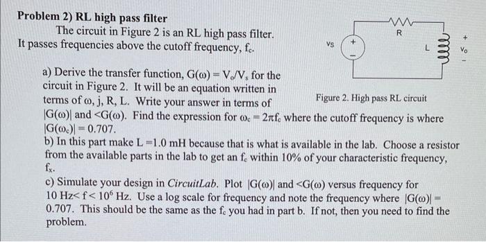
roblem 2) RL high pass filter The circuit in Figure 2 is an RL high pass filter. passes frequencies above the cutoff frequency, \( f_{c} \). a) Derive the transfer function, \( \mathrm{G}(\omega)=\mathrm{V}_{d} / \mathrm{V}_{\mathrm{s}} \) for the circuit in Figure 2. It will be an equation written in terms of \( \omega, \mathrm{j}, \mathrm{R}, \mathrm{L} \). Write your answer in terms of Figure 2. High pass RL circuit \( |\mathrm{G}(\omega)| \) and \( <\mathrm{G}(\omega) \). Find the expression for \( \omega_{\mathrm{c}}=2 \pi \mathrm{f}_{\mathrm{c}} \) where the cutoff frequency is where \( \left|\mathrm{G}\left(\omega_{\mathrm{c}}\right)\right|=0.707 \) b) In this part make \( \mathrm{L}=1.0 \mathrm{mH} \) because that is what is available in the lab. Choose a resistor from the available parts in the lab to get an \( \mathrm{f}_{\mathrm{c}} \) within \( 10 \% \) of your characteristic frequency, \( \mathrm{f}_{\mathrm{x}} \). c) Simulate your design in CircuitLab. Plot \( |G(\omega)| \) and \(
Expert Answer
Answer:- The answer for the