Home /
Expert Answers /
Electrical Engineering /
refer-to-figure-63-and-wire-three-7402-nor-gates-as-shown-note-that-a-short-between-the-ou-pa646
(Solved): Refer to Figure 63, and wire three 7402 NOR gates as shown. Note that a short between the ou ...
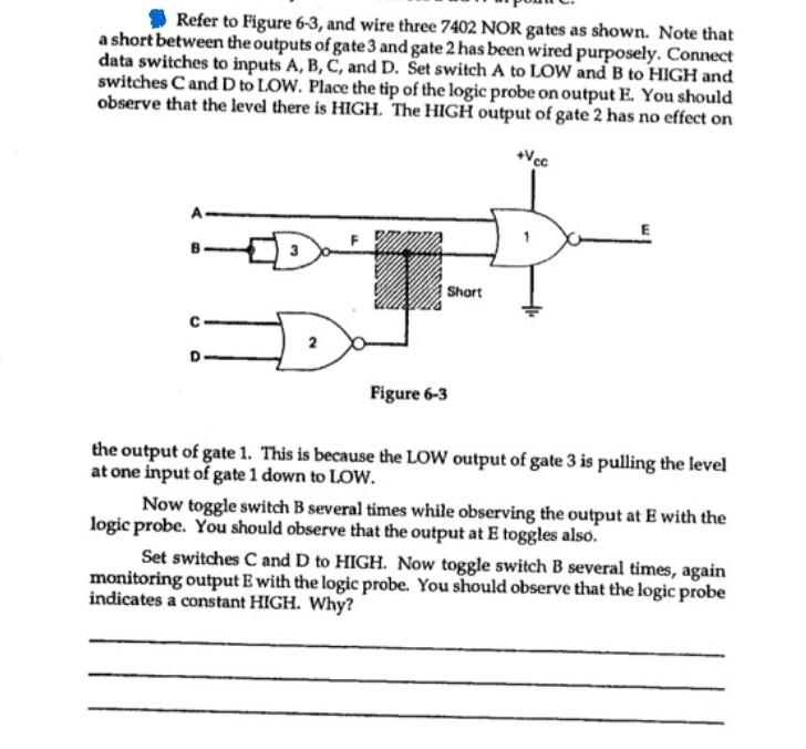
Refer to Figure , and wire three 7402 NOR gates as shown. Note that a short between the outputs of gate 3 and gate 2 has been wired purposely. Connect data switches to inputs A, B, C, and D. Set switch A to LOW and B to HIGH and switches C and D to LOW. Place the tip of the logic probe on output . You should observe that the level there is HIGH. The HIGH output of gate 2 has no effect on the output of gate 1. This is because the LOW output of gate 3 is pulling the level at one input of gate 1 down to LOW. Now toggle switch B several times while observing the output at with the logic probe. You should observe that the output at toggles also. Set switches C and D to HIGH. Now toggle switch B several times, again monitoring output with the logic probe. You should observe that the logic probe indicates a constant HIGH. Why?