Home /
Expert Answers /
Electrical Engineering /
q1-a-consider-the-common-emitter-ce-npn-transister-ampifier-shown-in-the-figure-1-and-state-th-pa485
(Solved): Q1 (a) Consider the common-emitter (CE) NPN transister ampifier shown in the figure 1 and state th ...
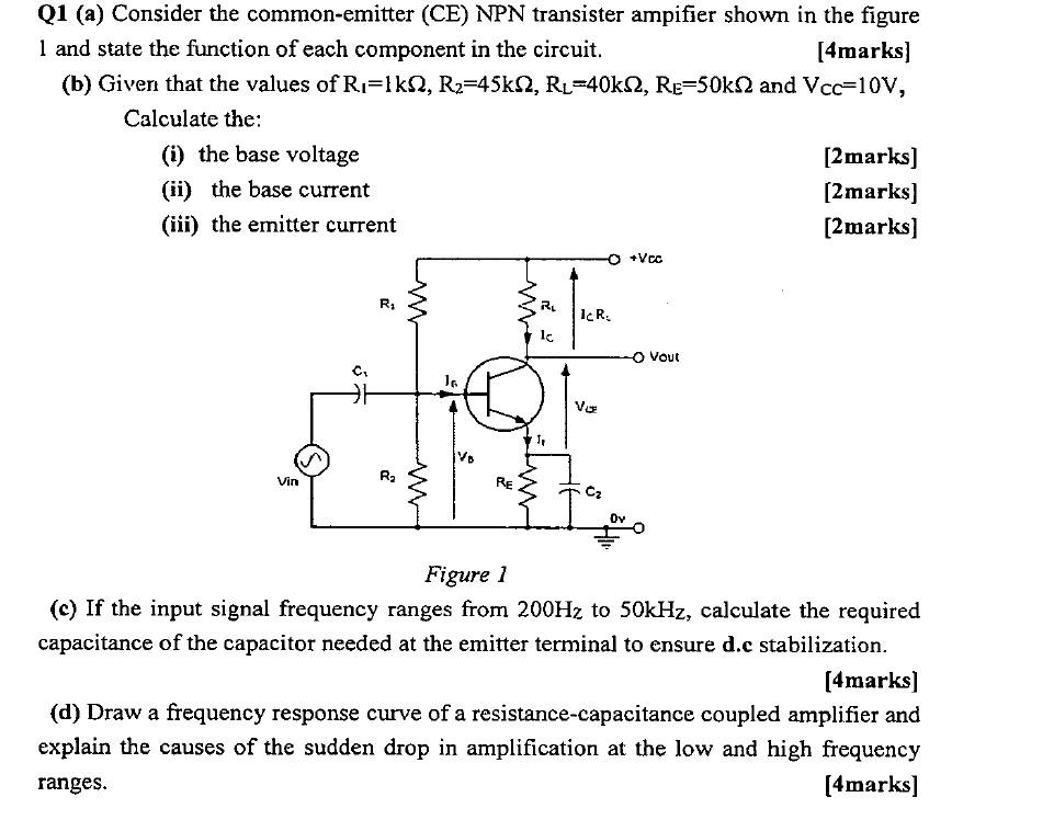
Q1 (a) Consider the common-emitter (CE) NPN transister ampifier shown in the figure 1 and state the function of each component in the circuit. [4marks] (b) Given that the values of \( R_{1}=1 \mathrm{k} \Omega, R_{2}=45 \mathrm{k} \Omega, R_{L}=40 \mathrm{k} \Omega, R_{E}=50 \mathrm{k} \Omega \) and \( V_{C C}=10 \mathrm{~V} \), Calculate the: (i) the base voltage [2marks] (ii) the base current [2marks] (iii) the emitter current [2marks] Figure 1 (c) If the input signal frequency ranges from \( 200 \mathrm{~Hz} \) to \( 50 \mathrm{kHz} \), calculate the required capacitance of the capacitor needed at the emitter terminal to ensure d.c stabilization. [4marks] (d) Draw a frequency response curve of a resistance-capacitance coupled amplifier and explain the causes of the sudden drop in amplification at the low and high frequency ranges. [4marks]