Home /
Expert Answers /
Civil Engineering /
problem-2-figure-shows-the-layers-of-soil-in-a-tube-100-mm-x-100-mm-in-cross-section-water-is-supp-pa310
(Solved): Problem 2 Figure shows the layers of soil in a tube 100 mm x 100 mm in cross-section water is supp ...
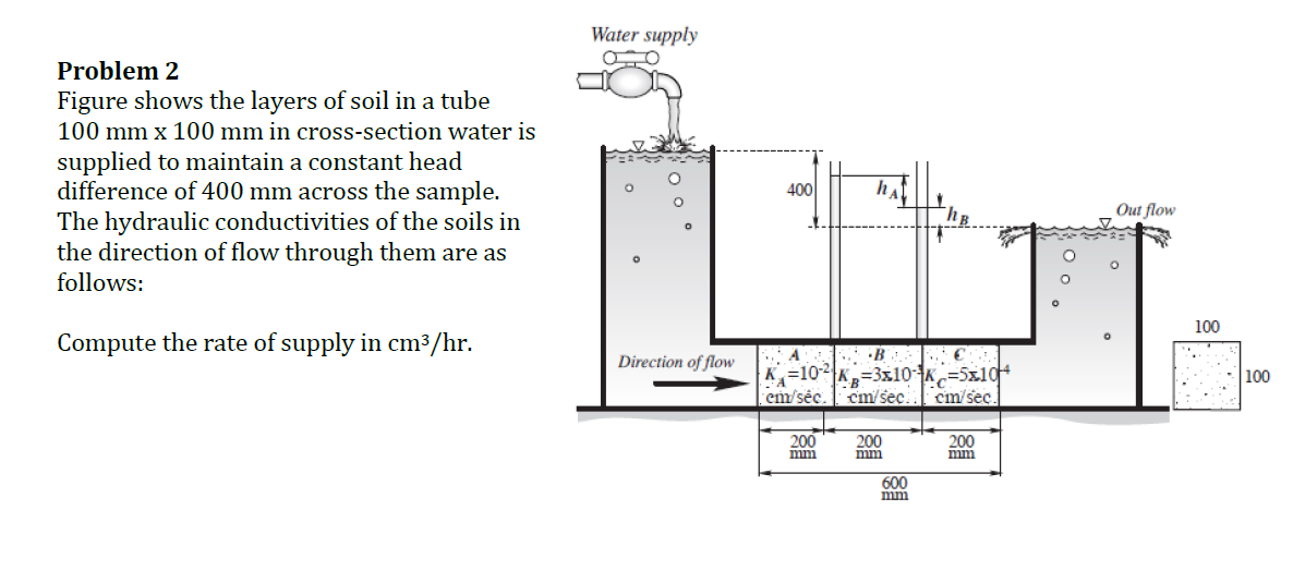
Problem 2 Figure shows the layers of soil in a tube 100 mm x 100 mm in cross-section water is supplied to maintain a constant head difference of 400 mm across the sample. The hydraulic conductivities of the soils in the direction of flow through them are as follows: Compute the rate of supply in cm³/hr. Water supply ao Direction of flow 400 A em s?c cm/sec. 200 200 hA ???? B C 2|K=3x10-¹K-S5x104 cm/sec. 200 ???? 600 ???? ????? ;00 Out flow O 100 100