Home /
Expert Answers /
Electrical Engineering /
please-use-the-breadboard-diagram-and-draw-the-circuit-of-the-first-figure-please-also-draw-circui-pa662
(Solved): Please use the breadboard diagram, and draw the circuit of the first figure. Please also draw circui ...
Please use the breadboard diagram, and draw the circuit of the first figure. Please also draw circuit of figure 3.
Will upvote, thank you!
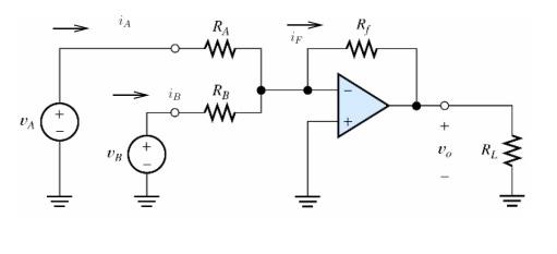
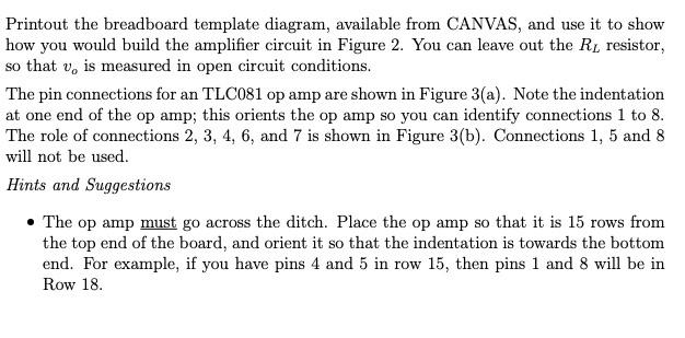
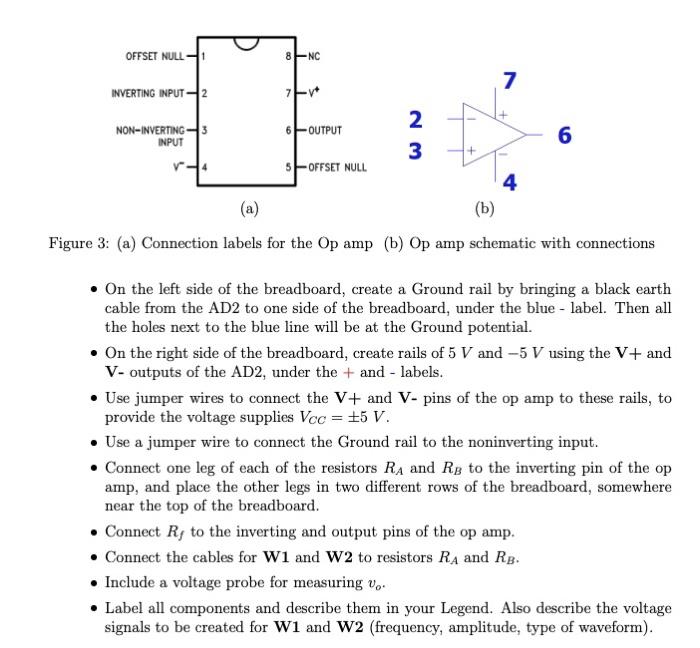
Printout the breadboard template diagram, available from CANVAS, and use it to show how you would build the amplifier circuit in Figure 2. You can leave out the resistor, so that is measured in open circuit conditions. The pin connections for an TLC081 op amp are shown in Figure 3(a). Note the indentation at one end of the op amp; this orients the op amp so you can identify connections 1 to 8 . The role of connections , and 7 is shown in Figure 3(b). Connections 1, 5 and 8 will not be used. Hints and Suggestions - The op amp must go across the ditch. Place the op amp so that it is 15 rows from the top end of the board, and orient it so that the indentation is towards the bottom end. For example, if you have pins 4 and 5 in row 15 , then pins 1 and 8 will be in Row 18.
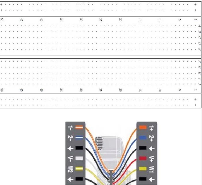
(a) (D) gure 3: (a) Connection labels for the amp (b) amp schematic with connections - On the left side of the breadboard, create a Ground rail by bringing a black earth cable from the AD2 to one side of the breadboard, under the blue-label. Then all the holes next to the blue line will be at the Ground potential. - On the right side of the breadboard, create rails of and using the and V- outputs of the AD2, under the + and - labels. - Use jumper wires to connect the and - pins of the op amp to these rails, to provide the voltage supplies . - Use a jumper wire to connect the Ground rail to the noninverting input. - Connect one leg of each of the resistors and to the inverting pin of the op amp, and place the other legs in two different rows of the breadboard, somewhere near the top of the breadboard. - Connect to the inverting and output pins of the op amp. - Connect the cables for and to resistors and . - Include a voltage probe for measuring . - Label all components and describe them in your Legend. Also describe the voltage signals to be created for W1 and W2 (frequency, amplitude, type of waveform).
Expert Answer
A BreadBoard is device which is used to connect electronic components temporarily. The breadboard has strips of metal underneath the board that connects the sockets(holes).A typical BreadBoard and it's internal connection layout is shown below