(Solved): *Please help with MULTISIM SIMULATION section. Please provide thorough explanations. Page 1 provided ...
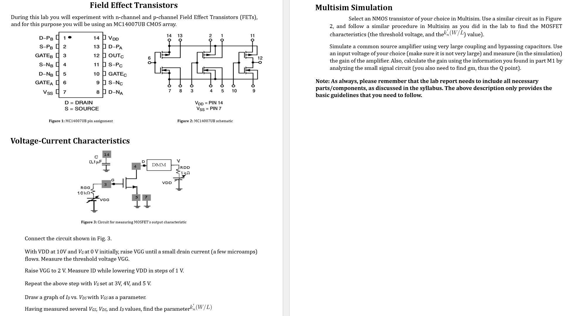
*Please help with MULTISIM SIMULATION section. Please provide thorough explanations. Page 1 provided for reference only. THANK YOU Field Effect Transistors During this lab you will experiment with n-channel and p-channel Field Effect Transistors (FETs), and for this purpose you will be using an MC14007UB CMOS array. Figure 1: MC14007UB pin assignment Figure 2: MC14007UB schematic Voltage-Current Characteristics Figure 3: Circuit for measuring MOSFET's output characteristic Connect the circuit shown in Fig. 3. With VDD at 10 V and V_(G) at 0 V initially, raise VGG until a small drain current (a few microamps) flows. Measure the threshold voltage VGG. Raise VGG to 2 V . Measure ID while lowering VDD in steps of 1 V . Repeat the above step with V_(G) set at 3V,4V, and 5 V . Draw a graph of I_(D) vs. V_(DS) with V_(GS) as a parameter. Having measured several V_(GS),V_(DS), and I_(D) values, find the parameter k_(n)^(')((W)/(L)) Multisim Simulation Select an NMOS transistor of your choice in Multisim. Use a similar circuit as in Figure 2, and follow a similar procedure in Multisim as you did in the lab to find the MOSFET characteristics (the threshold voltage, and the k_(n)^(')(W//L) value). Simulate a common source amplifier using very large coupling and bypassing capacitors. Use an input voltage of your choice (make sure it is not very large) and measure (in the simulation) the gain of the amplifier. Also, calculate the gain using the information you found in part M1 by analyzing the small signal circuit (you also need to find gm, thus the Q point).