Home /
Expert Answers /
Electrical Engineering /
part-a-analysis-of-an-op-amp-circuit-using-a-realistic-circuit-model-for-an-ideal-op-amp-we-assu-pa401
(Solved): Part A - Analysis of an op-amp circuit using a realistic circuit model For an ideal op-amp, we assu ...
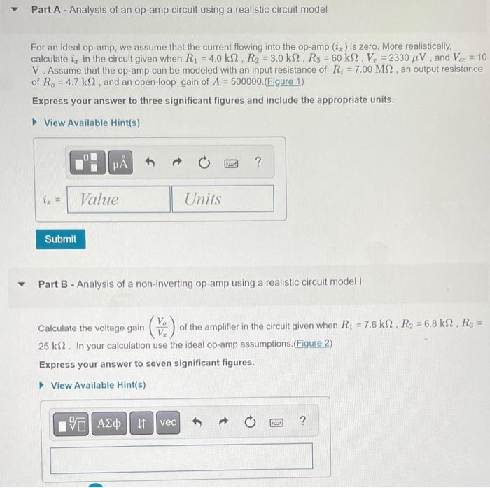
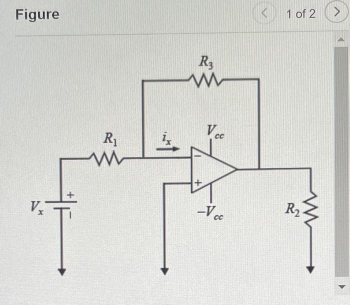
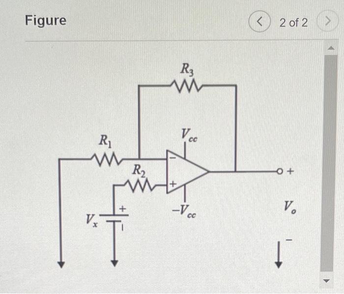
Part A - Analysis of an op-amp circuit using a realistic circuit model For an ideal op-amp, we assume that the current flowing into the op-amp \( \left(i_{x}\right) \) is zero. More realistically. calculate \( i_{x} \) in the circuit given when \( R_{1}=4.0 \mathrm{k} \Omega, R_{2}=3.0 \mathrm{k} \Omega, R_{3}=60 \mathrm{k} \Omega, V_{x}=2330 \mu \mathrm{V} \), and \( V_{c c}=10 \) \( \mathrm{V} \). Assume that the op-amp can be modeled with an input resistance of \( R_{i}=7.00 \mathrm{M} \Omega \), an output resistance of \( R_{0}=4.7 \mathrm{k} \Omega \), and an open-loop gain of \( A=500000 \).(Figure 1) Express your answer to three significant figures and include the appropriate units. Part B - Analysis of a non-inverting op-amp using a realistic circuit model I Calculate the voltage gain \( \left(\frac{V_{o}}{V_{x}}\right) \) of the amplifier in the circuit given when \( R_{1}=7.6 \mathrm{k} \Omega, R_{2}=6.8 \mathrm{k} \Omega, R_{3}= \) \( 25 \mathrm{k} \Omega \). In your calculation use the ideal op-amp assumptions.(Figure 2) Express your answer to seven significant figures.
Figure 1 of 2
2 of 2