(Solved): Open Channel Hydraulics Question 1 (50 marks) The channel system shown in Figure 1 was designed to s ...
Open Channel Hydraulics
Question 1 (50 marks)
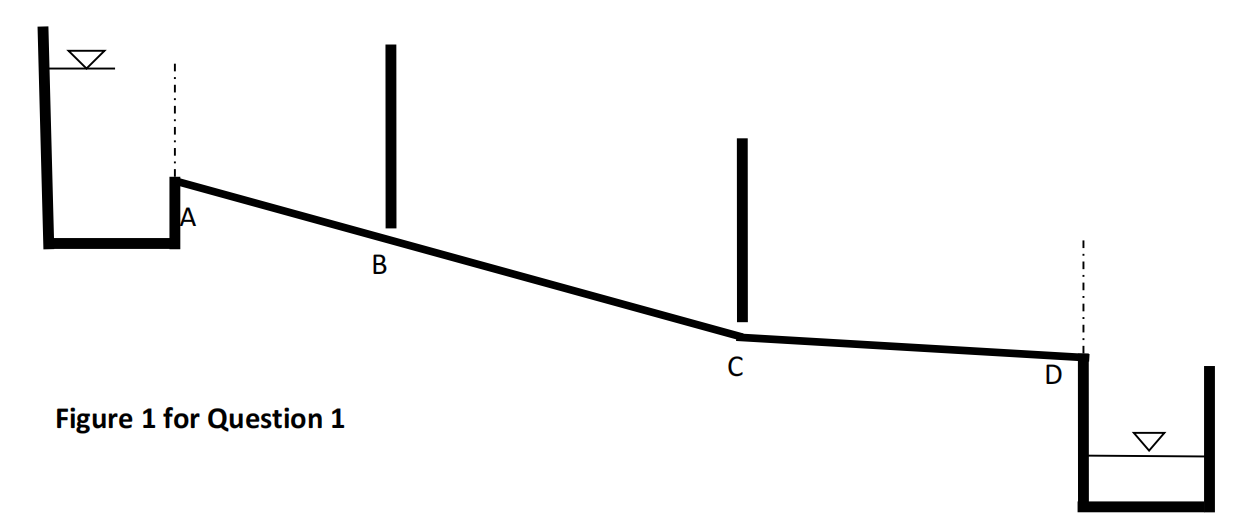
The channel system shown in Figure 1 was designed to supply water from an upstream reservoir at A to the downstream reservoir at D. Due to the varying topography, the channel was designed in two segments; ABC (SABC = S01) and CD (SCD = S02) of different bed slopes. Both segments are many kilo meters long so that there is an opportunity to come back to equilibrium state (where applicable) after flow transitions. There are two gates to control the flow and the flow depth at the vena contractor after each gate is approximately dv m. Energy loss due to flow passing through a gate can be neglected. This concrete lined (Manning’s roughness = n) rectangular channel (width = b m) delivers Q m3 /s.
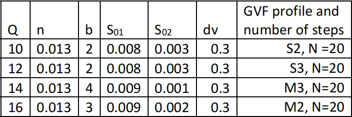
Choose any line , select Q, n, b, So1, So2 and dv from Table 1
Answer the following questions by demonstrating your working out clearly and logically
1. Compute uniform flow depths, critical depth and critical slope of this channel system and decide slope types
2. Sketch and name all possible water surface profiles. Indicate every possible flow changing location along the channel from Reservoir A to D (Start from the vertical dotted line at A). Note: use landscape orientation of the paper to draw profiles. Location name should be in the form of A1, A2, B1, B2, ….. etc.
3. Compute and tabulate, flow depths at every possible flow changing locations (clearly indicate any assumptions made and show your calculations clearly)
4. Calculate properties (d1, d2, height of the jump (Hj), length of the jump (Lj)and energy loss (DeltaE)) of any selected hydraulic jump.
5. Plot a typical “depth versus specific energy (d vs Es)” curve (not to scale) and indicate varying flow depth (dn1, dn2, dc, d1, d2, dv, dup) at appropriate locations of the plot. Note: Actual specific energy values are not expected, but relative positions should be accurate.
6. You are asked to compute length of a gradually varied flow profile using the Direct Step Method in N number of steps. The last column of Table 1 allocates
you a profile type and the number of steps (N) to be used in the analysis. Calculate value of DeltaD for this profile computation. State clearly the values of
the starting and the finishing depths used for DeltaD computation.
7. Using the Direct Step Method of gradually varied flow profile computation, calculate DeltaL1 and DeltaL2. Your working out in the step 1 of the Direct Step
Method needs to be clearly and logically presented.