Home /
Expert Answers /
Electrical Engineering /
nodal-and-mesh-network-analysis-simulation-and-implemenation-this-experiment-is-designed-to-asses-pa627
(Solved): NODAL, AND MESH NETWORK ANALYSIS, SIMULATION AND IMPLEMENATION This experiment is designed to asses ...
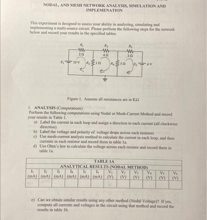
NODAL, AND MESH NETWORK ANALYSIS, SIMULATION AND IMPLEMENATION This experiment is designed to assess your ability in analyzing, simulating and implementing a multi-source circuit. Please perform the following steps for the network below and record your results in the specified tables. Figure 1. Assume all resistances are in \( \mathrm{K} \Omega \) 1. ANALYSIS (Computations) Perform the following computations using Nodal or Mesh-Current Method and record your results in Table 1. a) Label the current in each loop and assign a direction to each current (all clockwise direction). b) Label the voltage and polarity of voltage drops across each resistors c) Use mesh-current analysis method to calculate the current in each loop, and then currents in each resistor and record them in table la. d) Use Ohm's law to calculate the voltage across each resistor and record them in table la. e) Can we obtain similar results using any other method (Nodal Voltage)? If yes, compute all currents and voltages in the circuit using that method and record the results in table \( 1 \mathrm{~b} \).
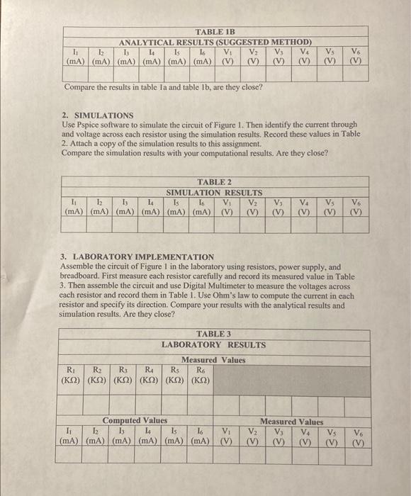
Compare the results in table la and table lb, are they close? 2. SIMULATIONS Use Pspice software to simulate the circuit of Figure 1. Then identify the current through and voltage across each resistor using the simulation results. Record these values in Table 2. Attach a copy of the simulation results to this assignment. Compare the simulation results with your computational results. Are they close? 3. LABORATORY IMPLEMENTATION Assemble the circuit of Figure 1 in the laboratory using resistors, power supply, and breadboard. First measure each resistor carefully and record its measured value in Table 3. Then assemble the circuit and use Digital Multimeter to measure the voltages across each resistor and record them in Table 1. Use Ohm's law to compute the current in each resistor and specify its direction. Compare your results with the analytical results and simulation results. Are they close?