(Solved): Need help with creating Use case Diagram, Use Case flow of events, Class Diagrams, and Class documen ...
Need help with creating Use case Diagram, Use Case flow of events, Class Diagrams, and Class documention on the requirements below, I filled out everything else need hlp with others though:
Here is known information:
You are to design a pizza order and delivery system for a new Pizza Shop. This is a brand new, "Mom and Pop" type, start-up operation. This shop is a pickup or delivery only business-- there is no restaurant dining. You are to design the whole computer system that will set up new customers, take orders, calculate bills, process payments, and contain the restaurant menu.
The following information is known:
1. You will set up a record for each new customer. This information will be keyed by customer phone number. Put information into the master record such as name, address, phone and type of charge account (Visa/ MasterCard). You also need to record pertinent information for locating the address (i.e., subdivision name, closest major intersection, etc.)
2. Your system needs to process payments in the form of checks, cash or credit cards. You will need to keep track of the type of payment made and the amount.
3. Users will access the customer database for all customer transactions. The information should come up for already established customers showing their address and delivery information.
4. Your system should be able to print out a receipt of the order with a place to sign the form by the customer if it is on a credit card. This should have customer information, a list of items ordered, if it is for delivery or pickup, and amount due.
5. Your system should contain the complete restaurant menu for order-taking purposes. The user needs to have GUI access to the various menu items and be able to quickly enter the desired orders. This menu needs to have various sizes of pizzas, the typical types of toppings, various crust options, and beverages. The customer should be able to order things like a medium, thin crust pizza, with pepperoni and extra cheese. This domain should be very familiar to you and if not, what better area to “research”?
Requirements Documention so far that needs help with Use case Diagram, Use Case flow of events, Class Diagrams, and Class documention on the requirements below:
Cover sheet/Title page
Requirements Documents <pg num>
Requirements Definition <pg num>
Requirement Specification Documents <pg num>
Use case diagram <pg num>
Use case flow of events <pg num>
Class diagrams <pg num>
Class documentation <pg num>
ER diagram(s) <pg num>
Decision table or state transition diagram <pg num>
Requirements Definition
<Each functional and non-functional requirement should follow the user story style and have a Unique ID (this will assist in the completion of the system design docs). >
- Functional Requirements
1.1 Unique ID: REQ-FUNC-001
- Requirement: The system must allow customers to create a new customer record.
- Description: Customers should be able to input their name, address, phone number, and choose a type of charge account, such as Visa or MasterCard. Additional information for address location, like subdivision name and closest major intersection, should be recorded.
1.2 Unique ID: REQ-FUNC-002
- Requirement: The system must process payments in the form of checks, cash, or credit cards.
- Description: The system should track the type of payment made (check, cash, or credit card) and the amount.
1.3 Unique ID: REQ-FUNC-003
- Requirement: The system must provide access to the customer database for all customer transactions.
- Description: Existing customer records should be accessible to show their address and delivery information.
1.4 Unique ID: REQ-FUNC-004
- Requirement: The system must print a receipt for orders.
- Description: The receipt should include customer information, a list of ordered items, indicate if the order is for delivery or pickup, and display the total amount due.
1.5 Unique ID: REQ-FUNC-005
- Requirement: The system must contain the complete restaurant menu.
Description: The menu should include various pizza sizes, toppings, crust options, and beverages. Customers should be able to specify details like medium size, thin crust, and specific toppings for their orders.
2. Non-Functional Requirements
2.1 Unique ID: REQ-NONFUNC-001
Requirement: Performance
Description: The system should handle a high volume of customer orders efficiently, ensuring quick order processing and response times.
2.2 Unique ID: REQ-NONFUNC-002
Requirement: Security
Description: The system should implement security measures to protect customer payment and personal information, ensuring data confidentiality.
2.3 Unique ID: REQ-NONFUNC-003
Requirement: Usability
Description: The user interface of the system should be intuitive and user-friendly, allowing both employees and customers to place orders with ease.Requirements Specification
1. Use Case Diagram
<Insert a Use case diagram or diagrams, if necessary, showing the actors and their interaction with the major functionalities of the system. If necessary, use more than one page rather than shrinking it to fit.>
2. Use Case Flow of Events
<Create the use case flow of events for each main flow from the use case diagram with preconditions, subflows and alternate flows>
3. Class Diagrams
<Insert the UML class diagrams for the system. At this point of development the diagrams should show the class name and the relationship between the classes (inheritance, dependency, association, aggregation, multiplicity. If necessary, use more than one page rather than shrinking it to fit.>
4. Class Documentation
<The class documentation should consist of 3 or 4 sentences describing the class, its functions and interactions.>
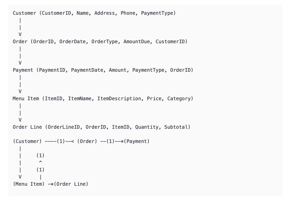
5. ER Diagram
<Insert the ER diagram using the classic design pattern, not tables, showing data and its relationships as it is stored in the database. If necessary, use more than one page rather than shrinking it to fit.>
ER Details:
Customer Entity:
Attributes:
• CustomerID (Primary Key)
• Name
• Address
• Phone
• PaymentType (e.g., Visa, MasterCard)
Order Entity:
Attributes:
• OrderID (Primary Key)
• OrderDate
• OrderType (Delivery/Pickup)
• AmountDue
Payment Entity:
Attributes:
• PaymentID (Primary Key)
• PaymentDate
• Amount
• PaymentType (e.g., Cash, Check, Credit Card)
Menu Item Entity:
Attributes:
• ItemID (Primary Key)
• ItemName
• ItemDescription
• Price
• Category (e.g., Pizza, Beverage)
Order Line Entity (This represents the items in an order):
Attributes:
• OrderLineID (Primary Key)
• OrderID (Foreign Key referencing Order)
• ItemID (Foreign Key referencing Menu Item)
• Quantity
• Subtotal
Relationships:
Customer-Order Relationship:
• One customer can place multiple orders, but each order is placed by one customer.
• Relationship Type: One-to-Many (1 Customer to Many Orders)
Order-Payment Relationship:
• An order can have one or more associated payments, but each payment is for one order.
• Relationship Type: One-to-Many (1 Order to Many Payments)
Order-Order Line Relationship:
• An order can have multiple order lines, representing the items in the order.
• Relationship Type: One-to-Many (1 Order to Many Order Lines)
Order Line-Menu Item Relationship:
• Each order line corresponds to one menu item, and a menu item can be part of multiple order lines.
• Relationship Type: Many-to-One (Many Order Lines to 1 Menu Item)
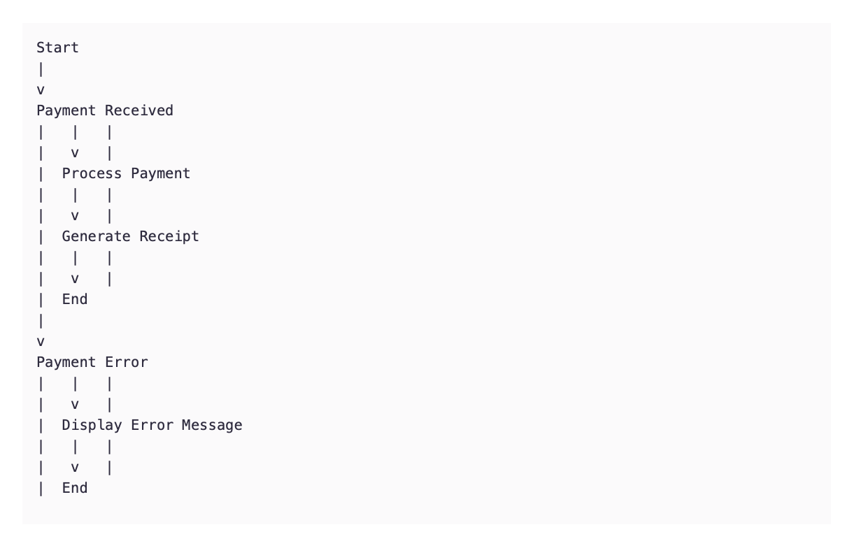
6. Decision Table or State Transition Diagram
<The decision table should be designed with the set of rules and conditions to support testing of the system. The state transition diagram should show the significant states of the system and events that cause the transition from one state to the next. If necessary, use more than one page rather than shrinking it to fit.>