Home /
Expert Answers /
Electrical Engineering /
nbsp-question-2-b-consider-the-5-bit-parallel-adder-circuit-shown-in-figure-2-assume-the-inp-pa537
(Solved): Question-2: b) Consider the 5-bit parallel adder circuit shown in Figure 2. Assume the inp ...
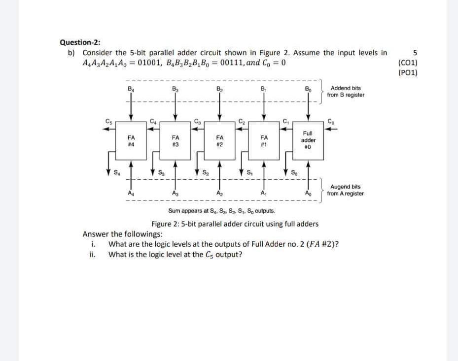
Question-2: b) Consider the 5-bit parallel adder circuit shown in Figure 2. Assume the input levels in \( A_{4} A_{3} A_{2} A_{1} A_{0}=01001, B_{4} B_{3} B_{2} B_{1} B_{0}=00111 \), and \( C_{0}=0 \) Figure 2: 5-bit parallel adder circuit using full adders Answer the followings: i. What are the logic levels at the outputs of Full Adder no. 2 (FA \#2)? ii. What is the logic level at the \( C_{5} \) output?
Expert Answer
Full adder table is as shown below: A B Cin S Cou