Home /
Expert Answers /
Electrical Engineering /
name-eee-202-lab-8-data-sheet-design-project-part-1-15-points-voltage-divider-design-what-do-pa877
(Solved): Name: EEE 202 Lab 8 Data Sheet Design Project Part 1 (15 points): Voltage Divider Design What do ...
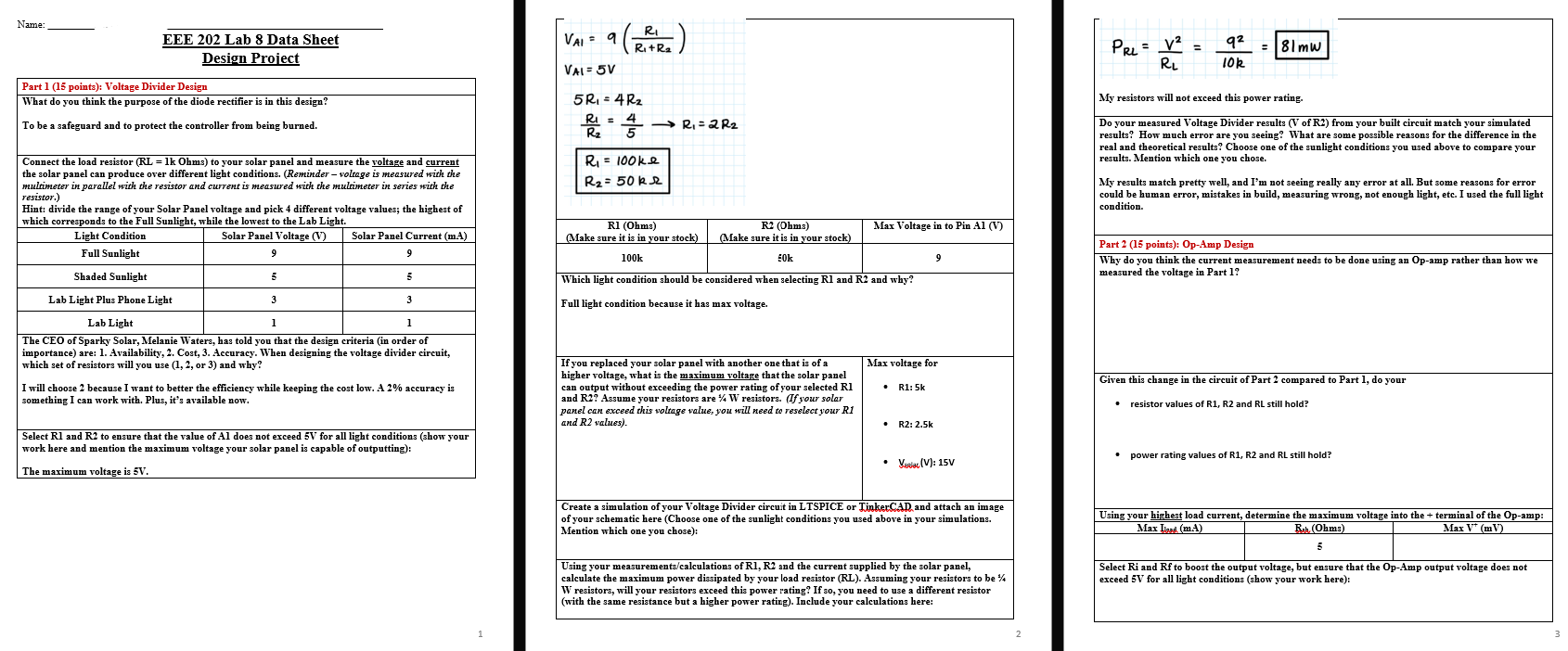
Name: EEE 202 Lab 8 Data Sheet Design Project Part 1 (15 points): Voltage Divider Design What do you think the purpose of the diode rectifier is in this design? To be a safeguard and to protect the controller from being burned. Connect the load resistor (RL = 1k Ohms) to your solar panel and measure the voltage and current the solar panel can produce over different light conditions. (Reminder - voltage is measured with the multimeter in parallel with the resistor and current is measured with the multimeter in series with the resistor.) Hint: divide the range of your Solar Panel voltage and pick 4 different voltage values; the highest of which corresponds to the Full Sunlight, while the lowest to the Lab Light. Light Condition Solar Panel Voltage (V) 9 Full Sunlight Shaded Sunlight Lab Light Plus Phone Light 5 Solar Panel Current (mA) 9 3 5 3 Lab Light 1 1 The CEO of Sparky Solar, Melanie Waters, has told you that the design criteria (in order of importance) are: 1. Availability, 2. Cost, 3. Accuracy. When designing the voltage divider circuit, which set of resistors will you use (1, 2, or 3) and why? I will choose 2 because I want to better the efficiency while keeping the cost low. A 2% accuracy is something I can work with. Plus, it's available now. Select R1 and R2 to ensure that the value of Al does not exceed 5V for all light conditions (show your work here and mention the maximum voltage your solar panel is capable of outputting): The maximum voltage is 5V. 1 1 (RRR? ) R?+R? VAI = 9 VAI = 5V 5R?=4R? R? R1 = 25 R? _ R? = 100ke R? = 50 kr R? = 2 R2 R1 (Ohms) (Make sure it is in your stock) 100k Which light condition should be considered when selecting R1 and R2 and why? Full light condition because it has max voltage. R2 (Ohms) (Make sure it is in your stock) 50k If you replaced your solar panel with another one that is of a higher voltage, what is the maximum voltage that the solar panel can output without exceeding the power rating of your selected R1 and R2? Assume your resistors are % W resistors. (If your solar panel can exceed this voltage value, you will need to reselect your R1 and R2 values). Max Voltage in to Pin A1 (V) Max voltage for • R1: 5k 9 . R2: 2.5k • Varia (V): 15V Create a simulation of your Voltage Divider circuit in LTSPICE or TinkerCAD and attach an image of your schematic here (Choose one of the sunlight conditions you used above in your simulations. Mention which one you chose): Using your measurements/calculations of R1, R2 and the current supplied by the solar panel, calculate the maximum power dissipated by your load resistor (RL). Assuming your resistors to be % W resistors, will your resistors exceed this power rating? If so, you need to use a different resistor (with the same resistance but a higher power rating). Include your calculations here: 2 PRL = V² RL 10k = 81mw My resistors will not exceed this power rating. Do your measured Voltage Divider results (V of R2) from your built circuit match your simulated results? How much error are you seeing? What are some possible reasons for the difference in the real and theoretical results? Choose one of the sunlight conditions you used above to compare your results. Mention which one you chose. My results match pretty well, and I'm not seeing really any error at all. But some reasons for error could be human error, mistakes in build, measuring wrong, not enough light, etc. I used the full light condition. Part 2 (15 points): Op-Amp Design Why do you think the current measurement needs to be done using an Op-amp rather than how we measured the voltage in Part 1? Given this change in the circuit of Part 2 compared to Part 1, do your resistor values of R1, R2 and RL still hold? power rating values of R1, R2 and RL still hold? Using your highest load current, determine the maximum voltage into the terminal of the Op-amp: Max Load (mA) Rah. (Ohms) Max V (mV) 5 Select Ri and Rf to boost the output voltage, but ensure that the Op-Amp output voltage does not exceed 5V for all light conditions (show your work here): 3
Ri (Ohms) Rf (Ohms) Gain (V/V) Max Vo (V) Why is a rail-to-rail Op-Amp required for this design? A rail-to-rail Op-Amp costs more than a standard Op-Amp, what value to the stakeholder does this extra feature add to the design? [Explain the benefits of rail-to-rail Op-Amps in your own words] Do the values of Ri and Rf need to be extremely accurate for your current measurement to be precise? Explain why or why not. Create a simulation of your Op-Amp circuit in LTSPICE or TinkerCAD and attach an image of your schematic here: Do your measured results from your built circuit match your simulated results? How much error are you seeing? What are some possible reasons for the difference in the real and theoretical results?

