Home /
Expert Answers /
Electrical Engineering /
lossy-integrator-1-for-the-lossy-integrator-in-fig-2-derive-the-time-domain-equation-for-the-o-pa227
(Solved): Lossy Integrator 1. For the lossy integrator in Fig. 2, derive the time-domain equation for the o ...
Lossy Integrator 1. For the lossy integrator in Fig. 2, derive the time-domain equation for the output in terms of the input. 2. Find R? to have a low-frequency gain of -22 if R? = 22k2 and C = 220nF, and calculate the 3-dB frequency. 3. Sketch the magnitude and phase Bode plots for the transfer function V?/V?. 4. Calculate Vo(t) for V;(t) = 0.5 sin(271000t). 5. Sketch the output waveform if the input is a 500mV 1kHz square wave signal.
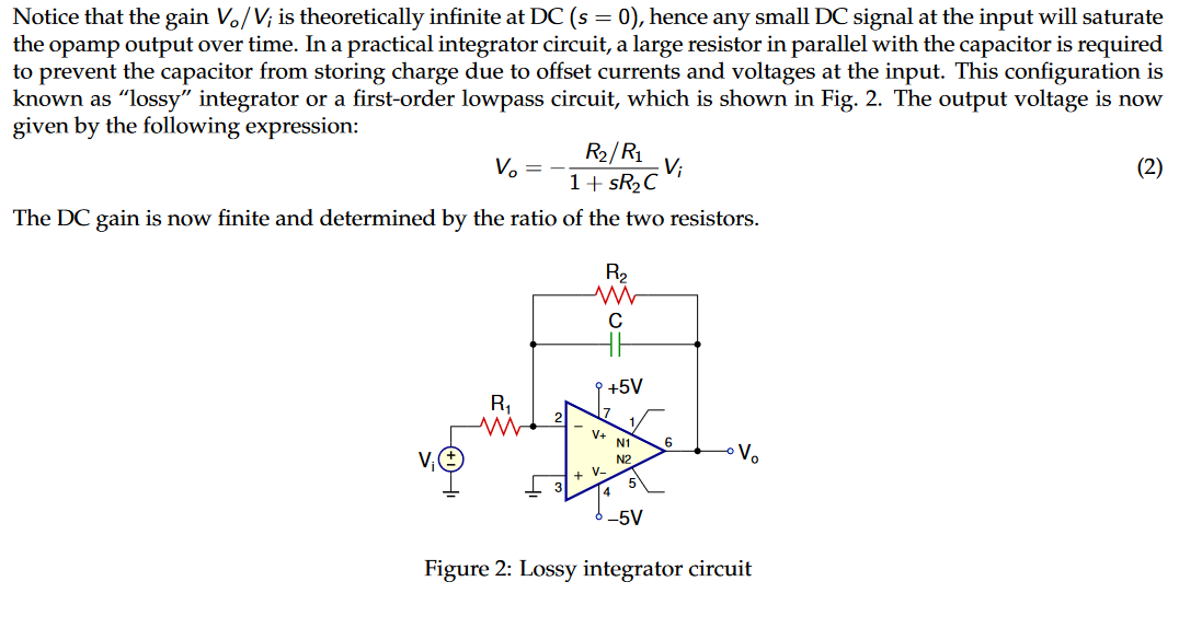
Notice that the gain V?/V; is theoretically infinite at DC (s = 0), hence any small DC signal at the input will saturate the opamp output over time. In a practical integrator circuit, a large resistor in parallel with the capacitor is required to prevent the capacitor from storing charge due to offset currents and voltages at the input. This configuration is known as "lossy" integrator or a first-order lowpass circuit, which is shown in Fig. 2. The output voltage is now given by the following expression: V? R?/R? ;V; 1+ sR? C The DC gain is now finite and determined by the ratio of the two resistors. R? C V+ + k +5V N1 N2 5 -5V 6 V? Figure 2: Lossy integrator circuit (2)