Home /
Expert Answers /
Electrical Engineering /
in-need-of-seeing-this-pin-diagram-circuit-on-tinkercad-please-refer-to-attached-images-question-pi-pa219
(Solved): In need of seeing this PIN diagram circuit on tinkercad. Please refer to attached images.Question:PI ...
In need of seeing this PIN diagram circuit on tinkercad. Please refer to attached images.
Question:
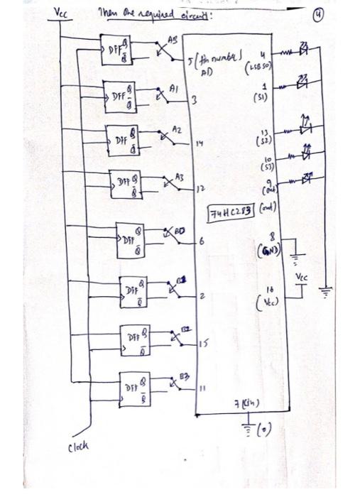
PIN Diagram:
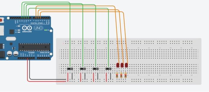
Tinkercad Example:
Also, please use arduino ! Just like the attached image, thank you!
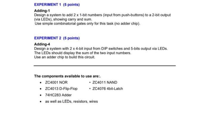
EXPERIMENT 1 (5 points) Adding-1 Design a system to add \( 2 \times 1 \)-bit numbers (input from push-buttons) to a 2-bit output (via LEDs), showing carry and sum. Use simple combinatorial gates only for this task (no adder chip). EXPERIMENT 2 (5 points) Adding \( -4 \) Design a system with \( 2 \times \) 4-bit input from DIP switches and 5-bits output via LEDs. The LEDs should display the sum of the two input numbers. Use an adder chip to build this circuit. The components available to use are: - ZC4001 NOR \( \quad \) ZC4011 NAND - ZC4013 D-Flip-Flop • ZC4076 4bit-Latch - 74HC283 Adder - as well as LEDs, resistors, wires