Home /
Expert Answers /
Electrical Engineering /
in-multisim-please-fig-1-simulate-the-circuit-by-connecting-the-input-of-logic-probe-to-logic-34-0-pa256
(Solved): In Multisim please Fig. 1. Simulate the circuit by connecting the input of logic probe to logic " 0 ...
In Multisim please
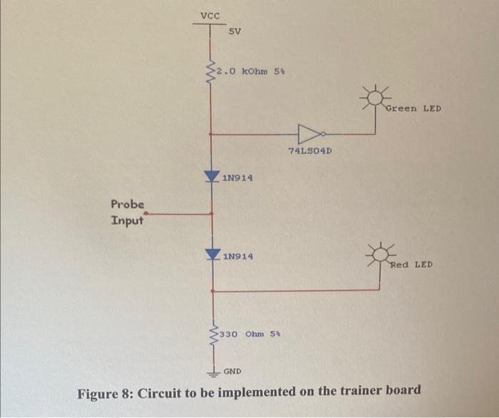
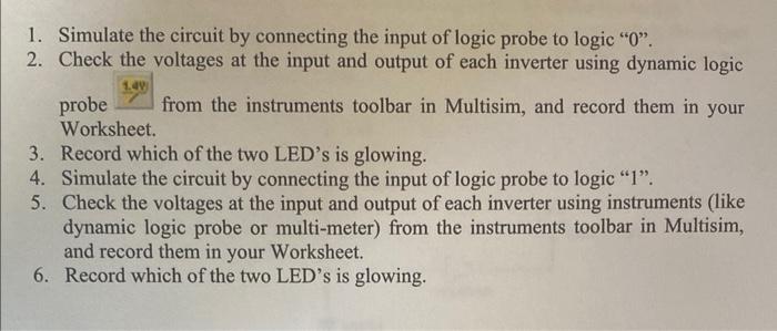
Fig.
1. Simulate the circuit by connecting the input of logic probe to logic " 0 ". 2. Check the voltages at the input and output of each inverter using dynamic logic probe \( \frac{1.40}{7} \) from the instruments toolbar in Multisim, and record them in your Worksheet. 3. Record which of the two LED's is glowing. 4. Simulate the circuit by connecting the input of logic probe to logic "1". 5. Check the voltages at the input and output of each inverter using instruments (like dynamic logic probe or multi-meter) from the instruments toolbar in Multisim, and record them in your Worksheet. 6. Record which of the two LED's is glowing.
Expert Answer
Case1: Logic 0 Inverter: input voltage=619