Home /
Expert Answers /
Electrical Engineering /
figure-q-3a-shows-a-two-quadrant-pwm-dc-dc-converter-circuit-which-drives-a-motor-the-converter-a-pa131
(Solved): Figure Q.3a shows a two-quadrant PWM DC-DC converter circuit which drives a motor. The converter a ...
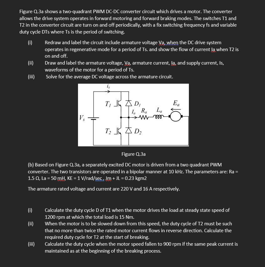
Figure Q.3a shows a two-quadrant PWM DC-DC converter circuit which drives a motor. The converter allows the drive system operates in forward motoring and forward braking modes. The switches T1 and T2 in the converter circuit are turn on and off periodically, with a fix switching frequency fs and variable duty cycle DTs where Ts is the period of switching. (i) (ii) (iii) (i) (ii) Redraw and label the circuit include armature voltage Va, when the DC drive system operates in regenerative mode for a period of Ts. and show the flow of current la when T2 is on and off. (iii) Draw and label the armature voltage, Va, armature current, la, and supply current, Is, waveforms of the motor for a period of Ts. Solve for the average DC voltage across the armature circuit. Vs T, JD, la Ra T? D? La voo Figure Q.3a (b) Based on Figure Q.3a, a separately excited DC motor is driven from a two quadrant PWM converter. The two transistors are operated in a bipolar manner at 10 kHz. The parameters are: Ra = 1.5 02, La = 50 mH, KE = 1 V/rad/sec, Jm + JL = 0.23 kgm2 The armature rated voltage and current are 220 V and 16 A respectively. Ea Calculate the duty cycle D of T1 when the motor drives the load at steady state speed of 1200 rpm at which the total load is 15 Nm. When the motor is to be slowed down from this speed, the duty cycle of T2 must be such that no more than twice the rated motor current flows in reverse direction. Calculate the required duty cycle for T2 at the start of breaking. Calculate the duty cycle when the motor speed fallen to 900 rpm if the same peak current is maintained as at the beginning of the breaking process.
