Home /
Expert Answers /
Mechanical Engineering /
figure-7-schematic-of-test-arrangement-used-to-measure-surface-pressure-acting-on-a-cylinder-ta-pa535
(Solved): Figure 7: Schematic of test arrangement used to measure surface pressure acting on a cylinder. Ta ...
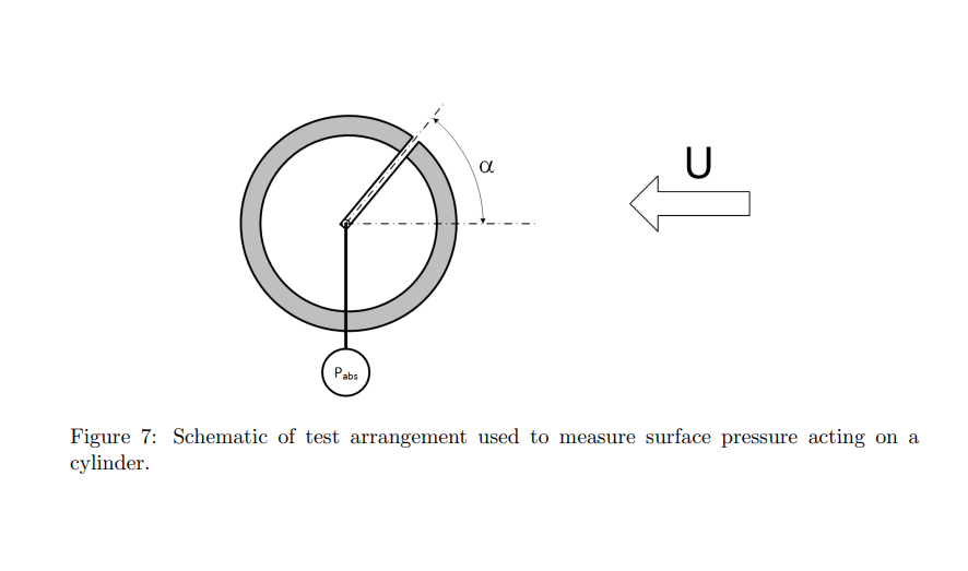
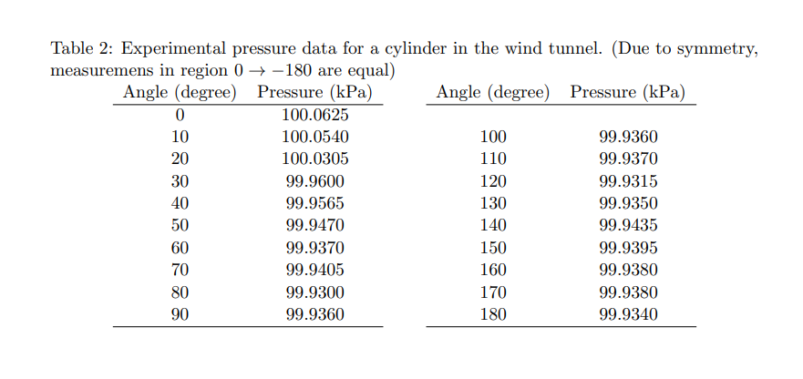
Figure 7: Schematic of test arrangement used to measure surface pressure acting on a cylinder.
Table 2: Experimental pressure data for a cylinder in the wind tunnel. (Due to symmetry, measuremens in region \( 0 \rightarrow-180 \) are equal)
Question 3: Experiments have been performed on a cylinder with a radius of \( 0.05 \mathrm{~m} \) in a wind tunnel, with pressure measurements made at several angles, \( \alpha \), as show in Fig. \( 7 . \) The corresponding absolute pressure readings are given in Tab. 2. The test was performed with an inflow velocity of \( 25 \mathrm{~ms}^{-1} \) and a static pressure measured at the windtunnel wall of \( 85 \mathrm{kPa} \) and the temperature is \( 25^{\circ} \mathrm{C} \). This question is to give you experience in the procedure required to calculate the forces on the airfoil in the experiment. This question is best answered using a spreadsheet (e.g. excel) or python, which can be used to plot the angular pressure variation and perform the numerical integration. Use the spreadsheet or python to do the following: - Use the pressure measurements to calculate and plot the pressure coefficient \( C_{p} \) as a function of angle, \( \alpha \). - By considering a segment \( d \alpha=10^{\circ} \) (e.g. a segment that extends from one measurment location to the next) on the surface of a cylinder with radius \( R_{0} \), draw a diagram to show how the pressure contributes to a surface force, \( d F \). - Resolve the force \( d F \) into horizontal and vertical components. - Use numerical integration (e.g. the trapezoidal rule from MECH2700) to obtain the net lift and drag forces acting on the cylinder.