Home /
Expert Answers /
Electrical Engineering /
figure-2-a-practical-compensated-integrator-show-that-the-transfer-function-for-the-fig-2-is-as-pa383
(Solved): Figure 2: A practical (compensated) integrator Show that the transfer function for the Fig. 2 is as ...
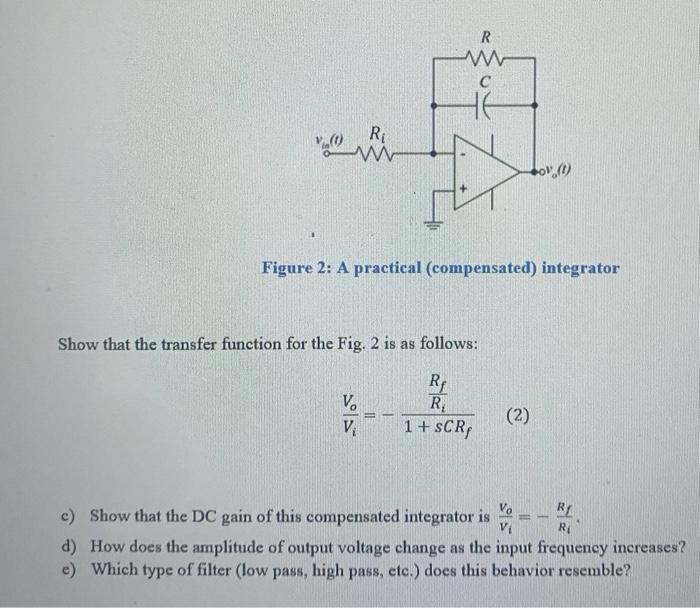
Figure 2: A practical (compensated) integrator Show that the transfer function for the Fig. 2 is as follows: \[ \frac{V_{o}}{V_{i}}=-\frac{\frac{R_{f}}{R_{i}}}{1+s C R_{f}} \] c) Show that the DC gain of this compensated integrator is \( \frac{V_{o}}{V_{i}}=-\frac{R_{f}}{R_{i}} \). d) How does the amplitude of output voltage change as the input frequency increases? e) Which type of filter (low pass, high pass, etc.) does this behavior resemble?