Home /
Expert Answers /
Electrical Engineering /
figure-2-2nd-order-op-amp-low-pass-filter-figure-2-shows-a-second-order-active-low-pass-filter-pa494
(Solved): Figure 2. 2nd order op-amp low pass filter. Figure 2 shows a second order active low pass filter. ...
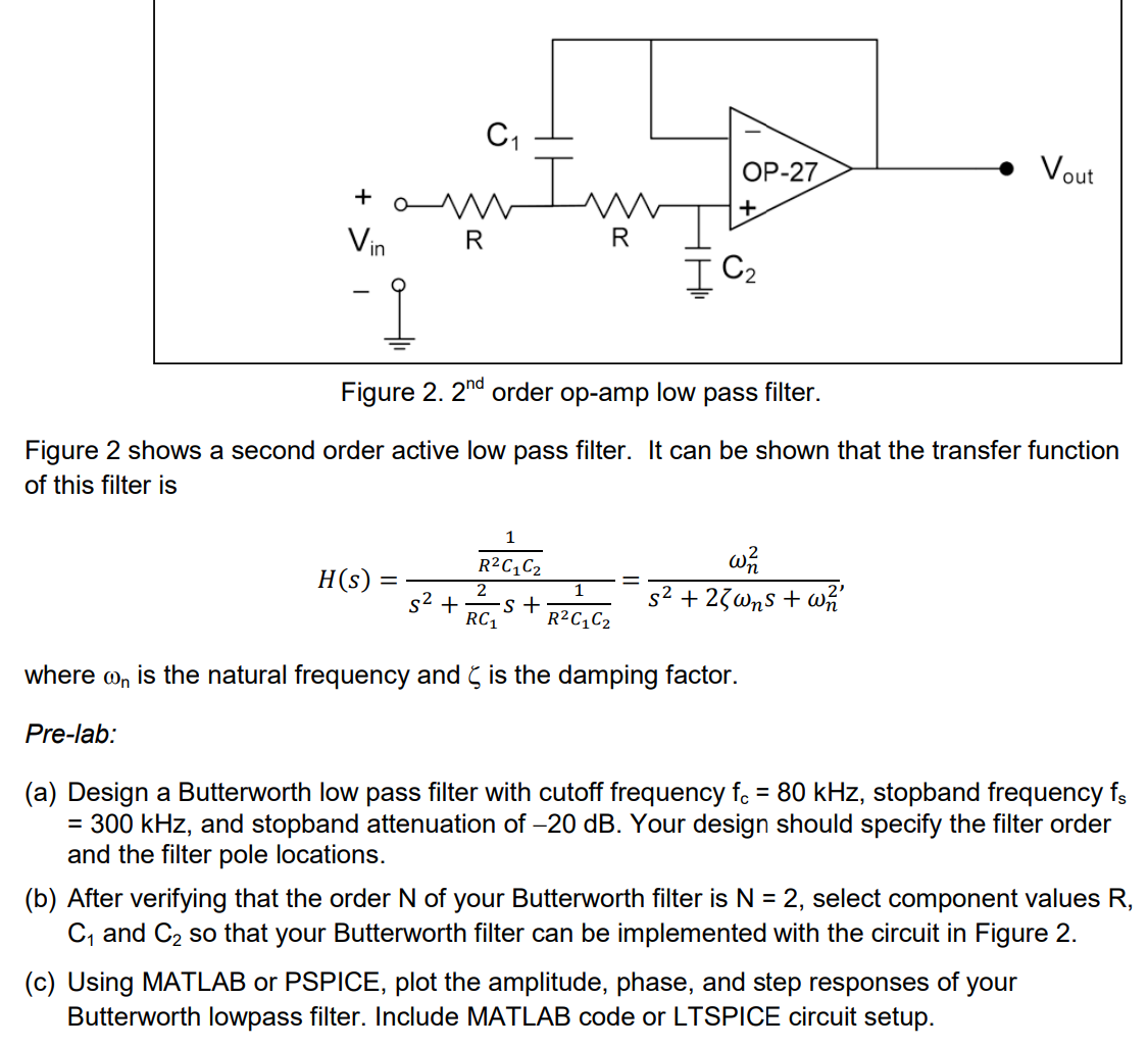
Figure 2. order op-amp low pass filter. Figure 2 shows a second order active low pass filter. It can be shown that the transfer function of this filter is where is the natural frequency and is the damping factor. Pre-lab: (a) Design a Butterworth low pass filter with cutoff frequency , stopband frequency , and stopband attenuation of . Your design should specify the filter order and the filter pole locations. (b) After verifying that the order of your Butterworth filter is , select component values , and so that your Butterworth filter can be implemented with the circuit in Figure 2. (c) Using MATLAB or PSPICE, plot the amplitude, phase, and step responses of your Butterworth lowpass filter. Include MATLAB code or LTSPICE circuit setup.