Home /
Expert Answers /
Advanced Math /
figure-1-demonstrates-the-inpu-output-configuration-for-an-lti-system-the-u-pa430
(Solved): Figure 1 demonstrates the inpu:-output configuration for an LTI system. The u ...
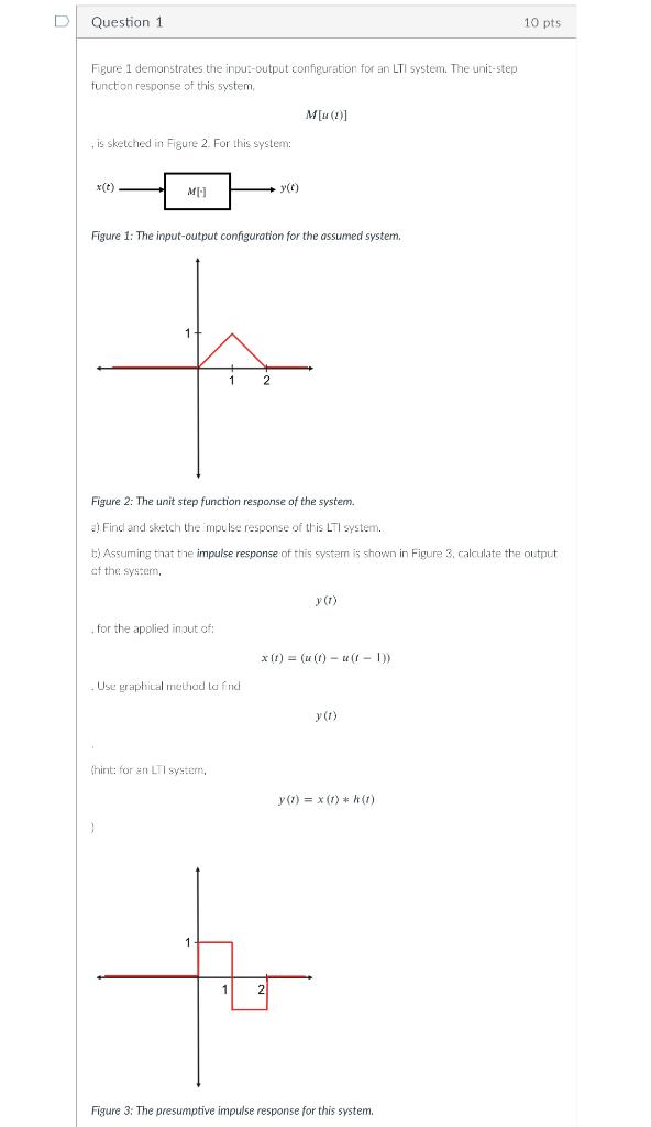
Figure 1 demonstrates the inpu:-output configuration for an LTI system. The unit-step tunct on response of this system, \[ M[u(t)] \] , is sketched in Figure 2 . For this system: Figure 1: The input-output configuration for the assumed system. Figure 2: The unit step function response of the system. di Find and sketch the mpulse response of th is LTI system. ti Assuming that the impulse response of this system is shown in Figure 3. calculate the output at the system, \( y(t) \) for the applied in out of: \[ x(t)=(u(t)-u(t-1)) \] Use graphical method to find \[ y(t) \] Thint: for en LTI system, \[ y(t)=x(t) * h(t) \] Figure 3: The presumptive impulse response for this system.
Expert Answer
The impulse response can be calculated from the fact that u(t)?u(t)=ramp(t) So the convolution of x(t)?h(t)=ramp(t),0?t?1 And a decreasing ramp means