Home /
Expert Answers /
Electrical Engineering /
figure-1-ac-chopper-circuit-with-on-off-control-and-voltage-form-for-question-5-6-7-8-9-10-a-10-o-pa361
(Solved): Figure 1: AC chopper circuit with ON-OFF control and voltage form For question 5-6-7-8-9-10: A 10-O ...
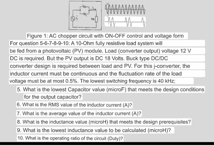
Figure 1: AC chopper circuit with ON-OFF control and voltage form For question 5-6-7-8-9-10: A 10-Ohm fully resistive load system will be fed from a photovoltaic (PV) module. Load (converter output) voltage \( 12 \mathrm{~V} \) \( \mathrm{DC} \) is required. But the PV output is DC 18 Volts. Buck type DC/DC converter design is required between load and PV. For this \( \mathrm{j} \)-converter, the inductor current must be continuous and the fluctuation rate of the load voltage must be at most \( 0.5 \% \). The lowest switching frequency is \( 40 \mathrm{kHz} \); 5. What is the lowest Capacitor value (microF) that meets the design conditions for the output capacitor? 6. What is the RMS value of the inductor current (A)? 7. What is the average value of the inductor current (A)? 8. What is the inductance value (microH) that meets the design prerequisites? 9. What is the lowest inductance value to be calculated (microH)? 10. What is the operating ratio of the circuit (Duty)?