Home /
Expert Answers /
Electrical Engineering /
fig-3-shows-a-typical-band-pass-active-filter-design-the-center-frequency-of-this-design-can-be-cal-pa397
(Solved): Fig 3 shows a typical band-pass active filter design. The center frequency of this design can be cal ...
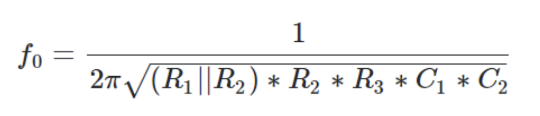
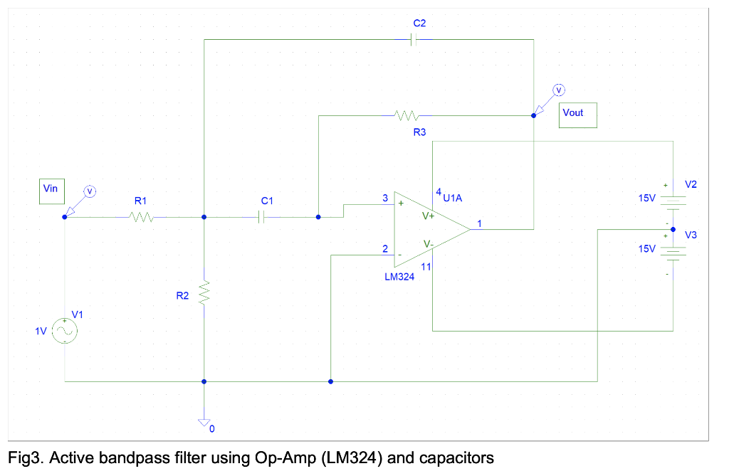
Fig 3 shows a typical band-pass active filter design. The center frequency of this design can be calculated using the following equation.
Design an active bandpass filter using the design in Fig 3. The center frequency should equal 79.8 kHz.
How would I find the resistor and capacitor values?
\( f_{0}=\frac{1}{2 \pi \sqrt{\left(R_{1} \| R_{2}\right) * R_{2} * R_{3} * C_{1} * C_{2}}} \)
Fig3. Active bandpass filter using Op-Amp (LM324) and capacitors
Expert Answer
We have For designing purpose, let R1 = R2 = 1 kohm which gi