Home /
Expert Answers /
Mechanical Engineering /
drive-the-mathematical-model-of-the-suspension-system-in-figure-1-as-per-the-following-schematic-d-pa282
(Solved): Drive the mathematical model of the suspension system in Figure 1 as per the following schematic d ...
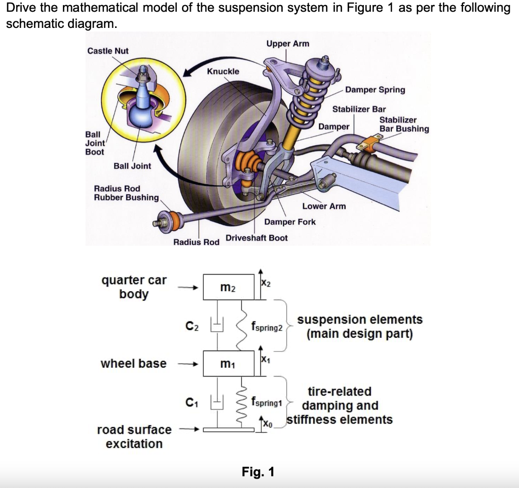
Drive the mathematical model of the suspension system in Figure 1 as per the following schematic diagram. Upper Arm Castle Nut Knuckle Damper Spring Stabilizer Bar Stabilizer Damper Bar Bushing Ball Joint Boot Ball Joint Radius Rod Rubber Bushing, Lower Arm Damper Fork Driveshaft Boot Radius Rod X2 quarter car body m2 C2 fspring2 suspension elements (main design part) wheel base X1 m1 C1 fspring1 tire-related damping and 9xo_stiffness elements road surface excit Fig. 1