Home /
Expert Answers /
Civil Engineering /
draw-the-shear-diagram-for-the-beam-follow-the-sign-convention-click-on-34-add-vertical-line-off-34-pa577
(Solved): Draw the shear diagram for the beam. Follow the sign convention. Click on "add vertical line off" ...
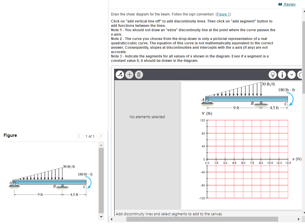
Draw the shear diagram for the beam. Follow the sign convention. Click on "add vertical line off" to add discontinuity lines. Then click on "add segment" button to add functions between the lines. Note 1 - You should not draw an "extra" discontinuity line at the point where the curve passes the \( x \)-axis. Note 2 - The curve you choose from the drop-down is only a pictorial representation of a real quadratic/cubic curve. The equation of this curve is not mathematically equivalent to the correct answer. Consequently, slopes at discontinuities and intercepts with the \( x \)-axis (if any) are not accurate. Note 3 - Indicate the segments for all values of \( x \) shown in the diagram. Even if a segment is a constant value 0 , it should be drawn in the diagram. No elements selected Add discontinuity lines and select segments to add to the canvas.
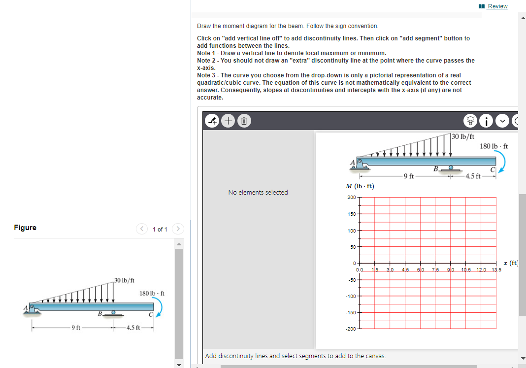
Draw the moment diagram for the beam. Follow the sign convention. Click on "add vertical line off" to add discontinuity lines. Then click on "add segment" button to add functions between the lines. Note 1 - Draw a vertical line to denote local maximum or minimum. Note 2 - You should not draw an "extra" discontinuity line at the point where the curve passes the \( x \)-axis. Note 3 - The curve you choose from the drop-down is only a pictorial representation of a real quadratic/cubic curve. The equation of this curve is not mathematically equivalent to the correct answer. Consequently, slopes at discontinuities and intercepts with the \( x \)-axis (if any) are not accurate. No elements selected IM \( (10 \cdot \mathrm{It}) \) Add discontinuity lines and select segments to add to the canvas.