Home /
Expert Answers /
Mechanical Engineering /
draw-the-ladder-logic-diagram-for-the-process-below-material-a-and-material-pa712
(Solved): Draw the Ladder Logic Diagram for the process below: Material A and Material ...
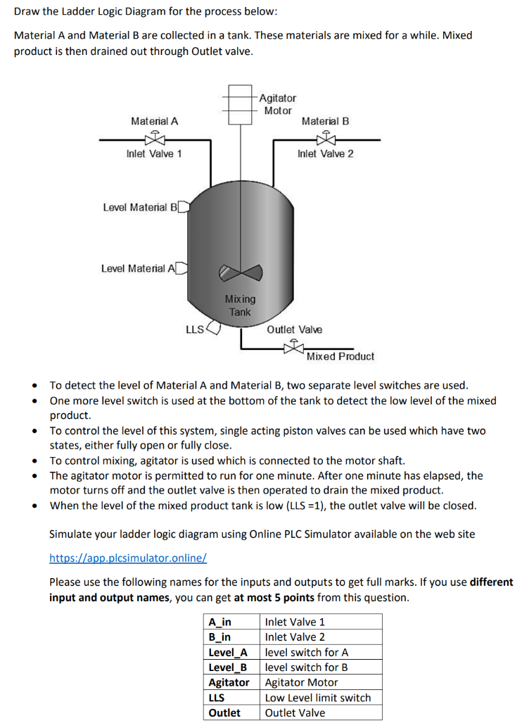
Draw the Ladder Logic Diagram for the process below: Material A and Material B are collected in a tank. These materials are mixed for a while. Mixed product is then drained out through Outlet valve. - To detect the level of Material A and Material B, two separate level switches are used. - One more level switch is used at the bottom of the tank to detect the low level of the mixed product. - To control the level of this system, single acting piston valves can be used which have two states, either fully open or fully close. - To control mixing, agitator is used which is connected to the motor shaft. - The agitator motor is permitted to run for one minute. After one minute has elapsed, the motor turns off and the outlet valve is then operated to drain the mixed product. - When the level of the mixed product tank is low (LLS =1), the outlet valve will be closed. Simulate your ladder logic diagram using Online PLC Simulator available on the web site Please use the following names for the inputs and outputs to get full marks. If you use different input and output names, you can get at most 5 points from this question.
Expert Answer
has two states, either fully open or fully close. To control mixing, agitator is used which is connected with Motor shaft. Particular time delay is ge