Home /
Expert Answers /
Electrical Engineering /
design-a-schematic-diagram-for-an-arduino-based-system-design-a-schematic-diagram-in-an-arduino-ma-pa352
(Solved): design a schematic diagram for an arduino based system. Design a schematic diagram in an arduino- ma ...
design a schematic diagram for an arduino based system.

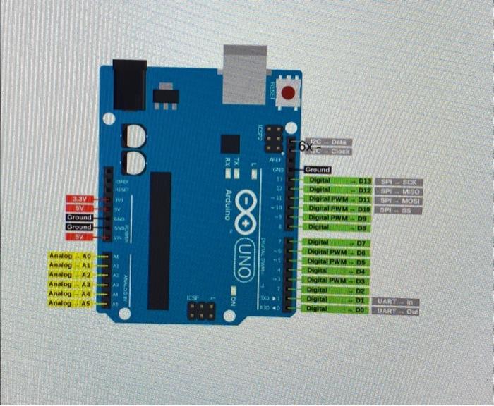
Design a schematic diagram in an arduino- mand sy stem to ran the given cade. (the pinad of the ardatio is 8 rovided he picture), you can determine the poripherad devices and connect then to the ardwine ports for performing the function int colloct const int sample Windew ; unsigneel int sample; Void setup () \{ Serial begin \}. Void loop() \{ Unsigned long startMillis = millis(); HES\}] unsigned int peak To peak ; consigned int signalMax =0; unsigned int signalMin ; While (millis() - starmillis < sampleWindow)
Expert Answer
To design a schematic diagram for the Arduino-based system running the provided code, you would need to connect the peripheral devices to the appropriate Arduino pins. Here's a suggested schematic diagram: +--------------------------------------------------+ | Arduino | +--------------------------------------------------+ | |