Home /
Expert Answers /
Electrical Engineering /
derive-the-transfer-function-of-the-integrator-circuit-shown-in-figure-p1-6-find-its-critical-fre-pa455
(Solved): Derive the transfer function of the integrator circuit shown in Figure P1.6. Find its critical fre ...
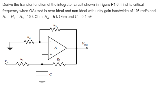
Derive the transfer function of the integrator circuit shown in Figure P1.6. Find its critical frequency when \( \mathrm{OA} \) used is near ideal and non-ideal with unity gain bandwidth of \( 10^{5} \mathrm{rad} / \mathrm{s} \) and \( R_{1}=R_{2}=R_{3}=10 \mathrm{k} \mathrm{Ohm}, R_{4}=5 \mathrm{k} \mathrm{Ohm} \) and \( C=0.1 \mathrm{nF} \)
Expert Answer
Solution Figure P1.6: An integrator circuit Transfer Function: The transfer function of the integrator circuit shown in Figure P1.6 is given by: