Home /
Expert Answers /
Electrical Engineering /
d-2-64-using-the-difference-amplifier-configuration-of-fig-2-16-and-assuming-an-ideal-op-amp-desi-pa286
(Solved): D 2.64 Using the difference amplifier configuration of Fig. 2.16 and assuming an ideal op amp, desi ...
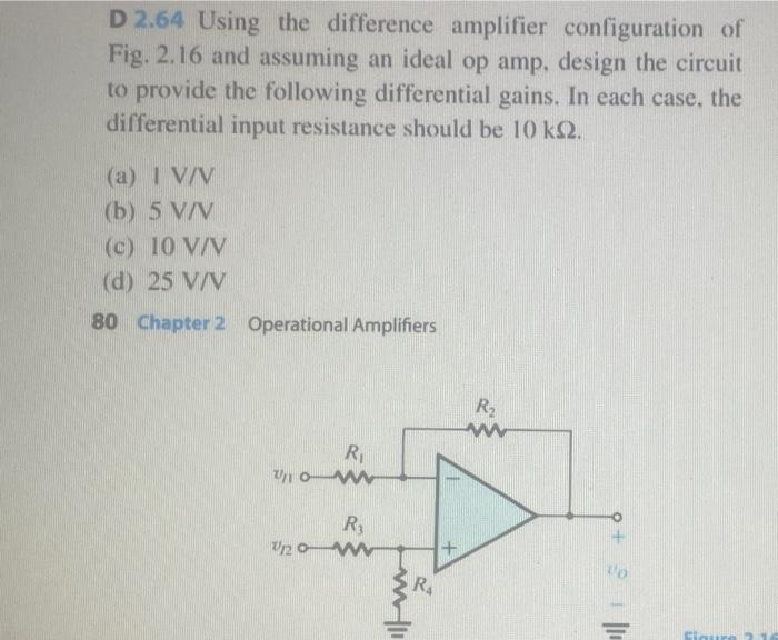
D 2.64 Using the difference amplifier configuration of Fig. 2.16 and assuming an ideal op amp, design the circuit to provide the following differential gains. In each case, the differential input resistance should be . (a) (b) (c) (d)
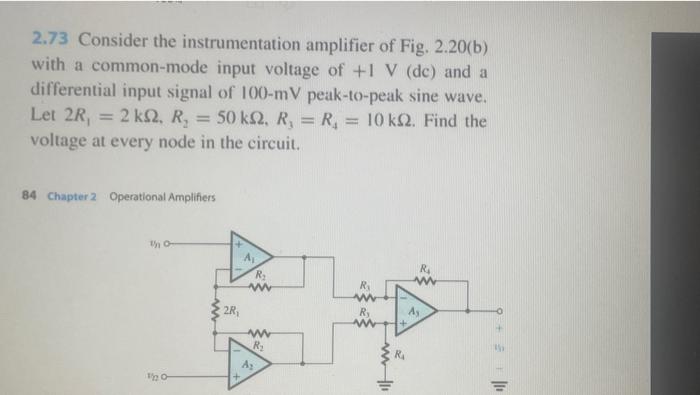
2.73 Consider the instrumentation amplifier of Fig. 2.20(b) with a common-mode input voltage of and a differential input signal of peak-to-peak sine wave. Let . Find the voltage at every node in the circuit. Chapter 2 Operational Amplifiers
D 2.82 Design a Miller integrator with a time constant of 1 and an input resistance of . A de voltage of volt is applied at the input at time 0 , at which moment . How long does it take the output to reach ? ?
Expert Answer
Answers?My dear friend pleas