Home /
Expert Answers /
Electrical Engineering /
consider-the-clamping-circuit-shown-below-the-periodic-signal-shown-has-been-applied-for-many-perio-pa301
(Solved): Consider the clamping circuit shown below. The periodic signal shown has been applied for many perio ...
Consider the clamping circuit shown below. The periodic signal shown has been applied for many periods
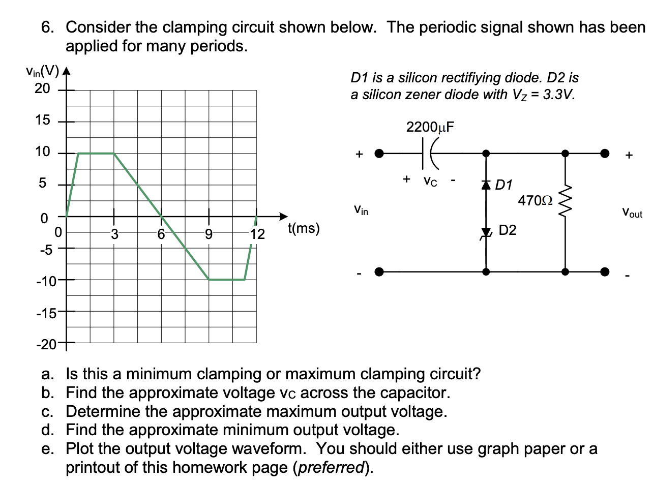
6. Consider the clamping circuit shown below. The periodic signal shown has been applied for many periods. is a silicon rectifiying diode. is a silicon zener diode with . a. Is this a minimum clamping or maximum clamping circuit? b. Find the approximate voltage vc across the capacitor. c. Determine the approximate maximum output voltage. d. Find the approximate minimum output voltage. e. Plot the output voltage waveform. You should either use graph paper or a printout of this homework page (preferred).