Home /
Expert Answers /
Electrical Engineering /
consider-the-block-diagram-of-an-antenna-control-system-shown-in-figure-p8-20-figure-p8-20-block-d-pa745
(Solved): Consider the block diagram of an antenna control system shown in Figure P8-20. Figure P8-20 Block d ...
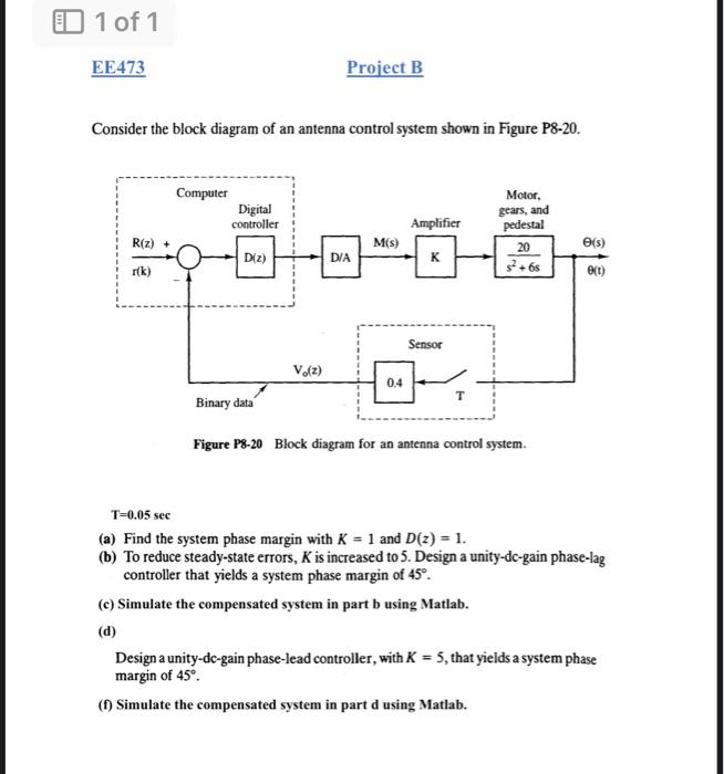
Consider the block diagram of an antenna control system shown in Figure P8-20. Figure P8-20 Block diagram for an antenna control system. \[ \mathrm{T}=0.05 \mathrm{sec} \] (a) Find the system phase margin with \( K=1 \) and \( D(z)=1 \). (b) To reduce steady-state errors, \( K \) is increased to 5 . Design a unity-dc-gain phase-lag controller that yields a system phase margin of \( 45^{\circ} \). (c) Simulate the compensated system in part b using Matlab. (d) Design a unity-dc-gain phase-lead controller, with \( K=5 \), that yields a system phase margin of \( 45^{\circ} \). (f) Simulate the compensated system in part d using Matlab.
Expert Answer
Hello student, I hope you your day is good. Your mentioned the question it was good, but you didn't mentioned the frequency response of g(s) of functi