Home /
Expert Answers /
Mechanical Engineering /
build-and-test-the-amplifier-circuit-shown-in-figure-1-measure-the-voltage-gain-using-the-osci-pa581
(Solved): Build and test the amplifier circuit shown in figure 1. Measure the voltage gain using the osci ...
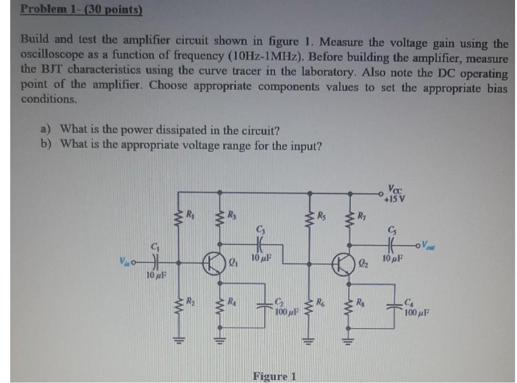
Build and test the amplifier circuit shown in figure 1. Measure the voltage gain using the oscilloscope as a function of frequency . Before building the amplifier, measure the BJT characteristics using the curve tracer in the laboratory. Also note the DC operating point of the amplifier. Choose appropriate components values to set the appropriate bias conditions. a) What is the power dissipated in the circuit? b) What is the appropriate voltage range for the input? Figure 1
Expert Answer
You must assemble and test the amplifier circuit depicted in figure 1 in order to answer the question. As part of the assi