Home /
Expert Answers /
Electrical Engineering /
b-figure-q2-b-i-shows-an-non-inverting-schmitt-trigger-comparator-while-figureq2-b-ii-shows-pa980
(Solved): b. Figure-Q2(b)(i) shows an non-inverting Schmitt trigger comparator, while FigureQ2(b) (ii) shows ...
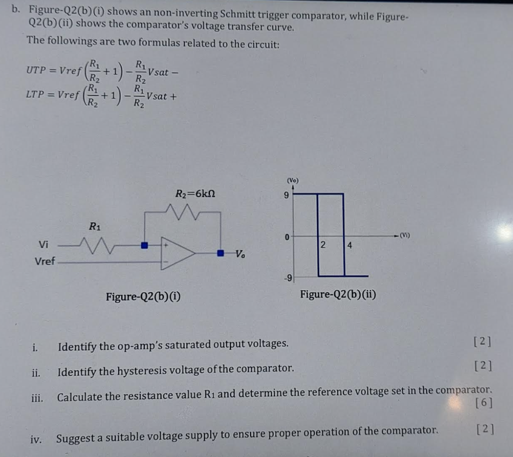
b. Figure-Q2(b)(i) shows an non-inverting Schmitt trigger comparator, while FigureQ2(b) (ii) shows the comparator's voltage transfer curve. The followings are two formulas related to the circuit: \[ \begin{array}{l} \text { UTP }=\operatorname{Vref}\left(\frac{R_{1}}{R_{2}}+1\right)-\frac{R_{1}}{R_{2}} V \text { sat }- \\ \text { LTP }=\operatorname{Vref}\left(\frac{R_{1}}{R_{2}}+1\right)-\frac{R_{1}}{R_{2}} V \text { sat }+ \end{array} \] i. Identify the op-amp's saturated output voltages. ii. Identify the hysteresis voltage of the comparator. [2] \( [2] \) iii. Calculate the resistance value \( \mathrm{R}_{1} \) and determine the reference voltage set in the comparator. [6] iv. Suggest a suitable voltage supply to ensure proper operation of the comparator.
Expert Answer
(i) * The upper saturation point that has been identified from the figure Q2)b) is * Vsat + = 9V * The lower saturation point that has been identified from the figure Q2)b) is * Vsat - = -9V (ii) The upper