Home /
Expert Answers /
Mechanical Engineering /
at-a-point-mathrm-a-above-the-neutral-axis-of-the-beam-shown-in-figure-1-the-state-of-plan-pa349
(Solved): At a point \( \mathrm{A} \) above the neutral axis of the beam shown in Figure 1, the state of plan ...
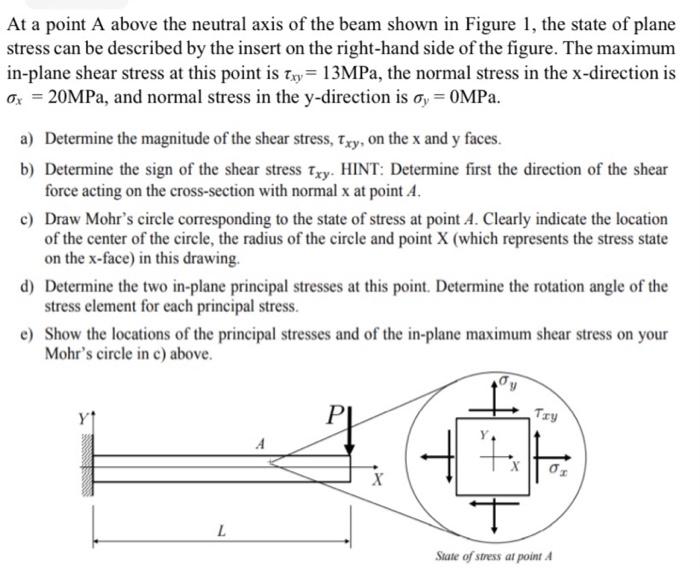
At a point \( \mathrm{A} \) above the neutral axis of the beam shown in Figure 1, the state of plane stress can be described by the insert on the right-hand side of the figure. The maximum in-plane shear stress at this point is \( \tau_{x y}=13 \mathrm{MPa} \), the normal stress in the x-direction is \( \sigma_{x}=20 \mathrm{MPa} \), and normal stress in the \( \mathrm{y} \)-direction is \( \sigma_{y}=0 \mathrm{MPa} \). a) Determine the magnitude of the shear stress, \( \tau_{x y} \), on the \( \mathrm{x} \) and \( \mathrm{y} \) faces. b) Determine the sign of the shear stress \( \tau_{x y} \). HINT: Determine first the direction of the shear force acting on the cross-section with normal \( \mathrm{x} \) at point \( A \). c) Draw Mohr's circle corresponding to the state of stress at point \( A \). Clearly indicate the location of the center of the circle, the radius of the circle and point \( \mathrm{X} \) (which represents the stress state on the \( x \)-face) in this drawing. d) Determine the two in-plane principal stresses at this point. Determine the rotation angle of the stress element for each principal stress. e) Show the locations of the principal stresses and of the in-plane maximum shear stress on your Mohr's circle in c) above.