Home /
Expert Answers /
Electrical Engineering /
a-in-the-scr-circuit-shown-in-the-figure-1-below-the-scr-has-a-latching-current-of-50-pa423
(Solved): a) In the SCR circuit shown in the Figure 1 below, the SCR has a latching current of \( 50 \ ...
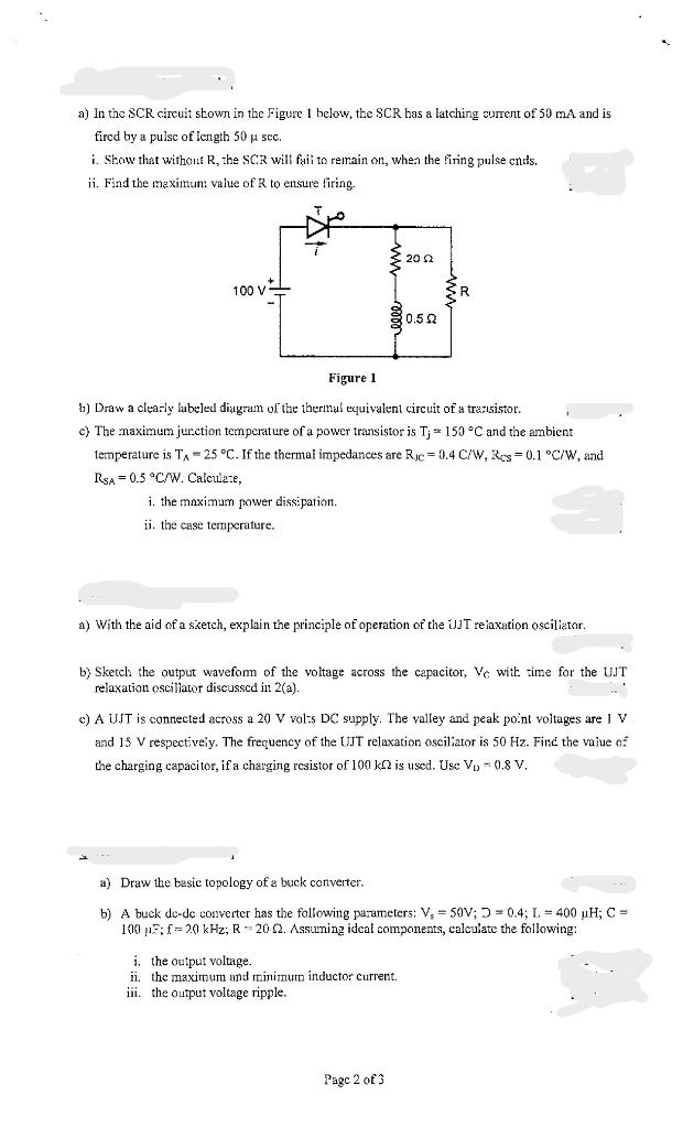
a) In the SCR circuit shown in the Figure 1 below, the SCR has a latching current of \( 50 \mathrm{~mA} \) and is fircd by a pulse of length \( 50 \mu \mathrm{scc} \). i. Show that without \( \mathrm{R} \), the \( \mathrm{SCR} \) will fuli to remain on, when the firing pulse cnds. ii. Find the theximun value of \( R \) to ensure firing. ?) Draw a cleaz-ly lubeled diagram ol the thermal equivalent circuit of a trezsistor. c) The maximum jurction temperature of a power transistor is \( T_{j}=150^{\circ} \mathrm{C} \) and the ambient temperature is \( \mathrm{T}_{\mathrm{A}}=25^{\circ} \mathrm{C} \). If the thermal impedances are \( \mathrm{RjC}=0.4 \mathrm{C} / \mathrm{W}, \mathrm{Res}_{\mathrm{cs}}=0.1^{\circ} \mathrm{C} / \mathrm{W} \), and \( \mathrm{R}_{\mathrm{SA}}=0.5^{\circ} \mathrm{C} N \). Calculate, i. the maximum power dissipation. ii. the case temperature. a) With the aid of a sietch, explain the principle of operation of the iJJ relaxation osciliator. b) Sketcl: the output wavefon of the voltage across the capacitor, V with time for the UJT relaxation oscillawr discusscd in 2(a). c) A U.IT is connected across a 20 V vol-s DC supply. The valley and peak point voltages are \( 1 \mathrm{~V} \) and \( 15 \mathrm{~V} \) respectively. The frequency of the UJT relaxation osciliator is \( 50 \mathrm{~Hz} \). Finc the vajue 0 : the charging capacitor, if a charging resistor of \( 100 \mathrm{k} \Omega \) is used. Use \( \mathrm{V}_{\mathrm{D}} \div 0,8 \mathrm{~V} \). a) Draw the basic topology of a buck converter. b) A buck dc-dc converter has the following parameters; \( V_{5}=50 \mathrm{~V} ; \Omega=0.4 ; L=400 \mu \mathrm{H} ; \mathrm{C}= \) \( 100 \mu F ; f=20 \mathrm{kHz} ; \mathrm{R}=20 \Omega \). Assuming ideal components, calculate the following: i. the output voltage. ii. the maximum and minimum inductor current. iii. the output voltage ripple.
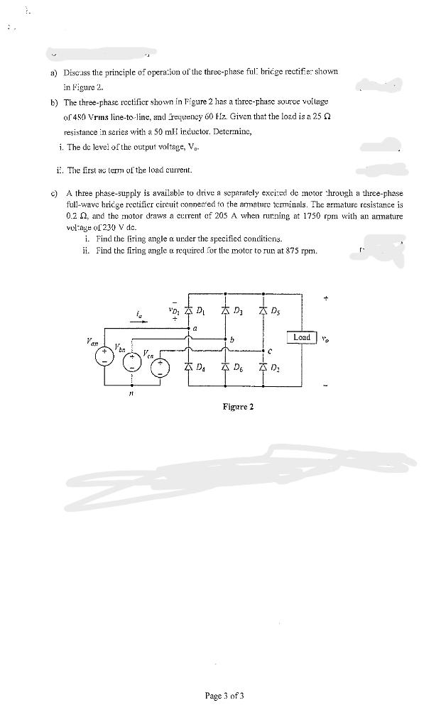
a) Disc' 'uss the principle of opera*ion of the three-phase ful bricge rectitie: shown in Figure 2. b) The three-phase rcctificr shown in Figure 2 has a threc-phase source vu[lage of 480 Vrms line-to line, and requency \( 60 \mathrm{fr} \). Given that the load is a \( 25 \Omega \) resistance in series with a \( 50 \mathrm{mH} \) irductor. Determinc, i. The dc level of the output voltage, \( V_{a} \). i. The first ac term of the load current. c) A three phase-supply is available to drive a separately excited de motor turough a three-phase full-wave bricge rectifier circuit connented to the armature terminals. The armature resistance is \( 0.2 \Omega \), and the motor draws a current of \( 205 \mathrm{~A} \) when rurning at \( 1750 \mathrm{rpm} \) with an armature vol-age o \( [23 y \mathrm{~V} \) dc. i. Find the firing angle \( \alpha \) urder the specified concitiens. ii. Find the firing angle \( \alpha \) required for the motor to run at \( 375 \mathrm{rpm} \).
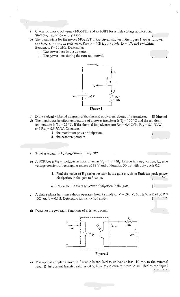
a) Given the choice between a MOSFET and an IGBT for a high voltage application. Stare your selection with reasons. b) The purameters lor the power MOSFEI in the circuit shown in the figure 1 are as follows: rise time, \( \mathrm{t}_{\mathrm{r}}=2,1 \mathrm{~s} \), on resistance; \( \mathrm{R}_{\mathrm{n} k(\text { al })}-0.2 \Omega \); duty cycle, \( \mathrm{D}=0.7 \); and switching frequency, \( f=30 \mathrm{kF} z \). De,ermine: i. The power-loss in the on state. ii. The power-loss during the tarn-an interval. c) Draw a clearly labeled diagram of the thermal equivalent circuit of \( s \) transistor. [8 Marks] d) The maximam junetion lemperalure ol a power transistor is \( T_{5}=150^{\circ} \mathrm{C} \) and the sanbiert temperatare is \( \mathrm{T}_{A}=25^{\circ} \mathrm{C} \). If the thersnal impedances are \( \mathrm{R}_{\mathrm{AC}}=0.4 \mathrm{C} / \mathrm{W}, \mathrm{R}_{\mathrm{C}}=9.1^{\circ} \mathrm{C} / \mathrm{W} \), and \( \mathrm{R}_{s_{A}}=0.5^{\circ} \mathrm{C} / \mathrm{W} \). Calcuiale, i. the maximum power dissipation. ii. the case temperature. a) What is moant by holding current in a SCR? b) A SCR hans a \( \mathrm{Vg} \) - Ig characteristics given as \( \mathrm{V}_{\mathrm{g}} \quad 1.5+8 \mathrm{I}_{\mathrm{g}} \). Ir a certain application, the gate voltage consists of rectangular puises \( \mathrm{O}^{2} 12 \mathrm{~V} \) and of duration \( 50 \mu \mathrm{S} \) with daty cycle \( 0.2 \). i. Find the value of Rg series resistor in the gate circuit to limit the peak power dissipation in the gate to 5 walts. ii. Calculate the average power dissipation in the gate. [ c) A single phuse half wave diode operates from a sujply of \( \mathrm{V}=240 \mathrm{~V}, 50 \mathrm{~Hz} \) to a load of \( \mathrm{R}= \) \( 10 \Omega \) and \( L=0.1 \mathrm{~L} \). Determine the extinction angle. d) Describe the two main futctions of a driver circuit. e) The optical coupler shown in figure 2 is required to deliver at least \( 10 \mathrm{~mA} \) to the external load. It the carrent transfer ratio is \( 60 \% \), how mach current must be supplied to the input?
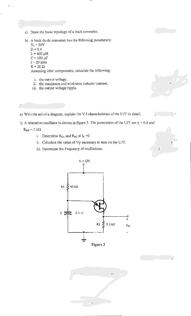
2) Traw the bassic inpology of a buck converter. b) A buck dc-dc converter bass the follouing parameters: \[ \begin{array}{l} V_{s}=50 \mathrm{~V} \\ \mathrm{D}=0.4 \\ \mathrm{~L}=400 \mu \mathrm{H} \\ \mathrm{C}=100 \mu \mathrm{F} \\ \mathrm{l}-20 \mathrm{kHz} \\ \mathrm{R}=20 \Omega \end{array} \] Assuming idea! components, calculate the following: i. the output voltage. ii. the maximum and minitmun inductor curent. iii. the output woltage ripple. a) With the aid of a diagram, cxplain the V-I characteristics of the UIT in detail. b) A relaxation oscillator is shown in figure 3 . The parameters of the UJT are \( \eta=0.6 \) and \( R_{\triangle B}=5 \mathrm{k} \Omega \). i. Delermine \( R_{B 1} \) and \( R_{D 2} \) at \( 1_{E}=0 \). ii. Calculate the value of \( \mathrm{Vp} \) necessary to turn on the UJT . iii. Determine the lequency of oscillations.