(Solved): A general fourbar linkage configuration and its notation are shown in the below figure. Thelink leng ...
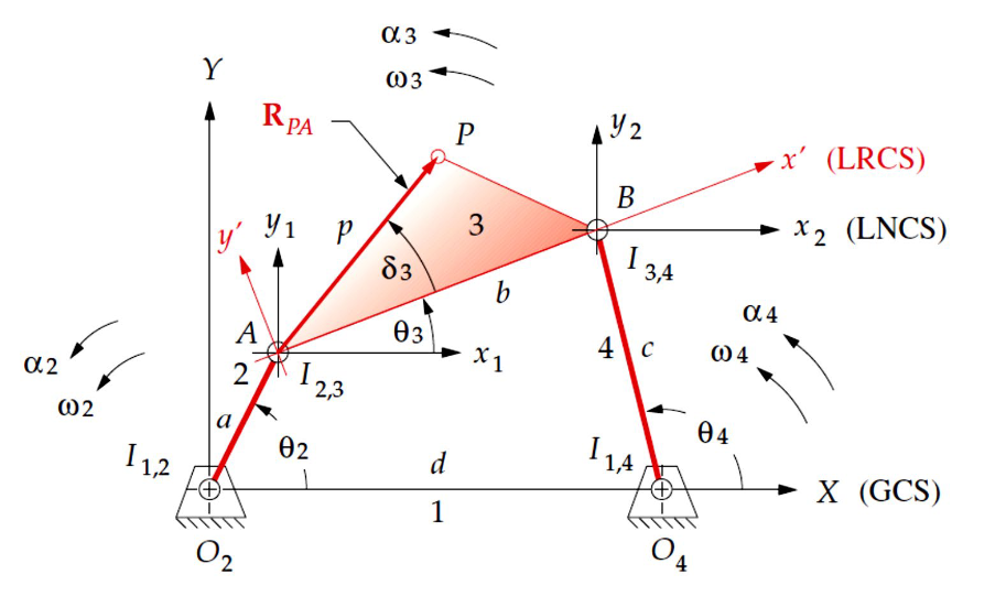
A general fourbar linkage configuration and its notation are shown in the below figure. The
link lengths, coupler point location, and the relevant values of distance and angles, including
????????2 and ???????? 2, are defined in the following table.
Parameters Values
Length of link 2, a (m) 1.115
Length of link 3, b (m) 2.5
Length of link 4, c (m) 2.5
Fixed point ????????4???????? (m) 2.67
Fixed point ????????4???????? (m) 0
Distance to coupler, AP, p (m) 1
????????3 (deg) -45
????????2 Start (deg) 0
????????2 End (deg) 90
???????? 2 (rad/s) 10 (counterclockwise)
(a) Calculate the horizontal position of the coupler point, ????????????????, with respect to the origin
global coordinate in ????????2 when the ????????2 = 0
(b) Calculate the horizontal velocity of the coupler point ???????????????????????? when the ????????2 = 0
(c) Calculate angular velocity ???????? 3 when the ????????2 = 0
(d) Calculate the horizontal acceleration of the pin joint ???????? ???????????????? when the ????????2 = 0