Home /
Expert Answers /
Mechanical Engineering /
a-draw-the-crank-slider-linkage-at-its-extreme-positions-marking-the-link-lengths-and-the-angles-pa433
(Solved): (a) Draw the crank slider linkage at its extreme positions marking the link lengths and the angles ...
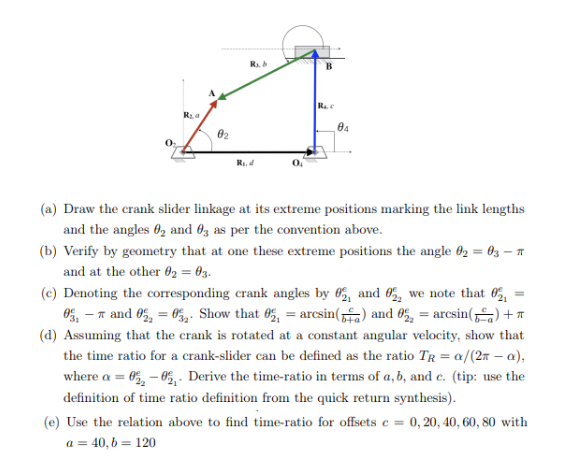
(a) Draw the crank slider linkage at its extreme positions marking the link lengths and the angles \( \theta_{2} \) and \( \theta_{3} \) as per the convention above. (b) Verify by geometry that at one these extreme positions the angle \( \theta_{2}=\theta_{3}-\pi \) and at the other \( \theta_{2}=\theta_{3} \). (c) Denoting the corresponding crank angles by \( \theta_{2_{1}}^{e} \) and \( \theta_{2_{2}}^{e} \) we note that \( \theta_{2_{1}}^{e}= \) \( \theta_{3_{1}}^{e}-\pi \) and \( \theta_{2_{2}}^{e}=\theta_{3_{2}}^{e} \). Show that \( \theta_{21}^{e}=\arcsin \left(\frac{c}{b+a}\right) \) and \( \theta_{22}^{e}=\arcsin \left(\frac{c}{b-a}\right)+\pi \) (d) Assuming that the crank is rotated at a constant angular velocity, show that the time ratio for a crank-slider can be defined as the ratio \( T_{R}=\alpha /(2 \pi-\alpha) \), where \( \alpha=\theta_{2_{2}}^{e}-\theta_{2_{1}}^{e} \). Derive the time-ratio in terms of \( a, b \), and \( c \). (tip: use the definition of time ratio definition from the quick return synthesis). (e) Use the relation above to find time-ratio for offsets \( c=0,20,40,60,80 \) with \( a=40, b=120 \)